With speed in data center changing from 10- to 40-Gbps and eventually to 100-Gbps, mobile and virtualized workloads, cloud applications, big data and heterogeneous devices are all demanding previously unimagined capacity and performance from servers and data center fabric. High-capacity optical technology and cabling infrastructure are required to support those servers and applications for 40-Gbps upgrading. Today’s article will mainly introduce pluggable optical Enhanced Quad Small Form-Factor Pluggable (QSFP+) modules, especially Bidirectional and parallel QSFP+ transceivers.
Brief Introduction to Optical Transceiver
The transceiver is an electronic device comprising both a transmitter and a receiver in the same circuity. This optical transceiver receives an electrical signal, converts it into a light signal, and launches the signal into a fiber. It also receives the light signal, from another transceiver, and converts it into an electrical signal. It is commonly known as GBIC, SFP, SFP+, XFP, CFP and QSFP+. The QSFP+ transceiver is the dominant transceiver form factor used for 40 Gigabit Ethernet applications. In 2010 the IEEE standard 802.3ba released several 40-Gbps based solutions, including a 40GBASE-SR4 parallel optics solution for MMF (FTL410QE2C is compatible Finisar 40GBASE-SR4 QSFP+ MMF transceiver with a link length of 150m). Since then, several engineered solutions have been released, including 40GBASE-CSR4, which is similar to 40GBASE-SR4 but extends the distance capabilities. Another solution is a bidirectional 40-Gbps transceiver that uses a two-fiber LC optical interface.
The transceiver is an electronic device comprising both a transmitter and a receiver in the same circuity. This optical transceiver receives an electrical signal, converts it into a light signal, and launches the signal into a fiber. It also receives the light signal, from another transceiver, and converts it into an electrical signal. It is commonly known as GBIC, SFP, SFP+, XFP, CFP and QSFP+. The QSFP+ transceiver is the dominant transceiver form factor used for 40 Gigabit Ethernet applications. In 2010 the IEEE standard 802.3ba released several 40-Gbps based solutions, including a 40GBASE-SR4 parallel optics solution for MMF (FTL410QE2C is compatible Finisar 40GBASE-SR4 QSFP+ MMF transceiver with a link length of 150m). Since then, several engineered solutions have been released, including 40GBASE-CSR4, which is similar to 40GBASE-SR4 but extends the distance capabilities. Another solution is a bidirectional 40-Gbps transceiver that uses a two-fiber LC optical interface.
Comparison of 40GBASE-SR4 Parallel Transceiver and Bidirectional Optical Transceivers
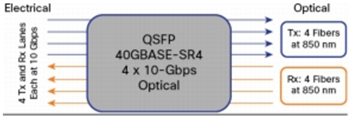
Parallel optical transceivers differ from traditional fiber optic transceivers in data center is simultaneously transmitted and received over multiple fibers. Used for 40GBASE-SR4 and 40GBASE-CSR4, this transceiver has 10-Gbps electrical lanes that are mirrored in the optical outputs and thus require eight fibers with an MTP connector interface. Each fiber either transmits (Tx) or receives (Rx) 10-Gbps traffic at a single wavelength. Figure 1 shows the electrical and optical lanes diagram of 40GBASE-SR4 QSFP+ transceiver.
Parallel optical transceivers differ from traditional fiber optic transceivers in data center is simultaneously transmitted and received over multiple fibers. Used for 40GBASE-SR4 and 40GBASE-CSR4, this transceiver has 10-Gbps electrical lanes that are mirrored in the optical outputs and thus require eight fibers with an MTP connector interface. Each fiber either transmits (Tx) or receives (Rx) 10-Gbps traffic at a single wavelength. Figure 1 shows the electrical and optical lanes diagram of 40GBASE-SR4 QSFP+ transceiver.

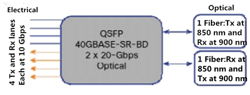
Bidirectional optical transceivers used for 40GBASE-SR-BD have the same 10-Gbps electrical lanes, which are then combined in the optical outputs, thus requiring two fibers with an LC connector interface. Each fiber simultaneously transmits and receives 20-Gbps traffic at two different wavelengths. Figure 2 shows a electrical and optical lanes diagram of bidirectional optical transceiver.

From the above images, we can easily see some differences between Bidirectional and parallel optical transceiver. This two-fiber 40-Gbps Bidirectional (BiDi) multimode solution uses two different transmission windows (850 nm and 900 nm) that are transmitted bidirectionally over the same fiber, which will allow the use of same cabling infrastructure for 40 Gigabit Ethernet as was used for 1 and 10G Ethernet application. While the parallel multimode optical transceiver operates at a wavelength of 850nm. In additional, the connector type was converted from the traditional 2-fiber LC duplex connector to a 12-fiber MTP connector.
Cabling Options for Parallel and Bidirectional Optical Modules
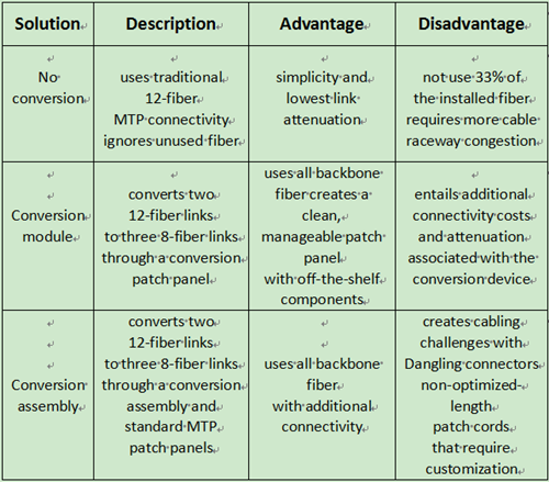
Choosing which type of fiber optical cable for your infrastructure is essential. As noted before, 40GBASE-SR4 multimode parallel optical transceiver uses eight fibers to transmit four duplex channels each at 10 Gigabit Ethernet. Parallel optical transceiver uses MTP 12-fiber trunk cable but only 8 of 12 fibers is used. There are several basic cabling options for parallel optics connectivity. I will generally introduce three solutions to you. One approach is to ignore the unused fibers and continue to deploy 12 fibers. Another approach is to use a conversion device to convert two 12-fiber links into three 8-fiber links. Figure 3 summarizes these three cabling solutions for 40G connectivity.
Choosing which type of fiber optical cable for your infrastructure is essential. As noted before, 40GBASE-SR4 multimode parallel optical transceiver uses eight fibers to transmit four duplex channels each at 10 Gigabit Ethernet. Parallel optical transceiver uses MTP 12-fiber trunk cable but only 8 of 12 fibers is used. There are several basic cabling options for parallel optics connectivity. I will generally introduce three solutions to you. One approach is to ignore the unused fibers and continue to deploy 12 fibers. Another approach is to use a conversion device to convert two 12-fiber links into three 8-fiber links. Figure 3 summarizes these three cabling solutions for 40G connectivity.

As for the pluggable Bidirectional transceiver, it has the same QSFP+ format as the existing 40GBASE-SR4 transceiver. Therefore, the same switch line card with QSFP+ ports can support either parallel optics 40GBASE-SR4 or bidirectional optics 40GBASE-SR-BD solutions. Thus, when directly connecting a 40 Gigabit Ethernet bidirectional transceiver to another bidirectional transceiver, a Type A-to-B standard LC duplex patch cord can be used. This reverse fiber positioning allows a signal to be directed from the transmit position on one end of the network to the receive position on the other end of the network. However, this type of direct connectivity is suggested only within a given row of cabinets.
Conclusion
40-Gbps performance is no longer a myth, but a truth that has already facilitated people's daily life. When transitioning from 10 to 40 Gigabit Ethernet, extended 40 Gigabit Ethernet link distances, which match the distances at 10 Gigabit Ethernet, can be achieved by parallel optics transceivers. And as to 40 Gigabit Ethernet bidirectional transceivers, no changes to the cabling infrastructure are required, which is a huge cost saving. Fiberstore offers a large variety of 40-Gbps parallel optical transceivers that are fully compatible with major brand like Finisar QSFP+. For more detailed information about our devices, please contact us directly.
40-Gbps performance is no longer a myth, but a truth that has already facilitated people's daily life. When transitioning from 10 to 40 Gigabit Ethernet, extended 40 Gigabit Ethernet link distances, which match the distances at 10 Gigabit Ethernet, can be achieved by parallel optics transceivers. And as to 40 Gigabit Ethernet bidirectional transceivers, no changes to the cabling infrastructure are required, which is a huge cost saving. Fiberstore offers a large variety of 40-Gbps parallel optical transceivers that are fully compatible with major brand like Finisar QSFP+. For more detailed information about our devices, please contact us directly.

No comments:
Post a Comment