Showing posts with label single-mode fiber. Show all posts

Thursday, June 29, 2017

OM5 WB MMF Vs 50 µm Laser Optimized OM4 Vs Single-Mode Fiber Cables

Network speeds like 40G and 100G Ethernet have already become the mainstream in data centers, and the industry is still working collaboratively on the next-generation development for higher density and faster speed. Multimode fibers, for example, are treated as the cost-effective solutions for short-reach optical interconnects. OM5 fiber, certificated in 2016, is know as the wide band multimode fiber (WBMMF) designed to carry signals over short wavelength (850nm to 950nm). Many enterprise IT and data center managers nowadays are adopting single-mode fiber system or OM4 cabling in the network infrastructure. Will OM5 MMF be a good alternative for 40G/100G network system? This article will provide the detailed information about OM5 fibers, and make a clear comparison between OM5, OM4 MMF and single-mode fiber cables.

OM5 fiber
Is OM5 WB MMF Fiber A Good Solution for Data Centers?
No exact answer can be provided here as OM5 MMF is still a new product in 2017.
OM5 MMF fiber has the same geometry as OM4: 50 µm of core size and 125 µm of cladding, which make it fully compatible and intermateable with OM3 and OM4 cabling. OM5 fiber specifies a wider range of wavelengths between 850 nm and 953 nm. The additional specifications of effective modal bandwidth and attenuation at 953 nm is identical to specification of OM4.
It was created to support Shortwave Wavelength Division Multiplexing (SWDM), which is one of the new technologies being developed for transmitting 40 Gb/s, 100 Gb/s, and beyond. With the use of SWDM technology, it is desirable to reduce parallel fiber count by at least a factor of four to allow continued use of just two fibers (rather than eight) for transmitting 40 Gb/s and 100 Gb/s and reduced fiber counts for higher speeds.

OM5 MMF Vs OM4
The 40/100GbE expected maximum operational distances of OM5 fiber is displayed in the above table. OM5 fiber can support longer distance of 440m for 40G SWDM, and 150m for 100G SWDM system.
How Does OM5 Differ From 50 µm Laser Optimized OM4 Fiber?
Wavelength—OM5 WB MMF is intended for operation using vertical-cavity surface-emitting laser (VCSEL) transceivers across the 846 to 953 nm wavelength range, while OM3 and OM4 50 micron laser optimized multimode fiber, whose bandwidth diminishes rapidly above the 850 nm operating wavelength.
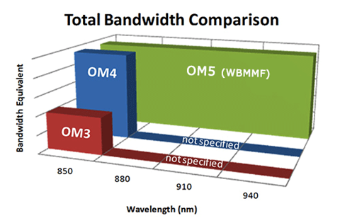
OM5_WideBand_Multimode_Fiber_Bandwidth_Comparison
Effective Modal Bandwidth (EMB)—the best system performance is achieved by a combination of low chromatic dispersion and high EMB. OM5 EMB values are specified as following at both 850 and 953 nm.
• EMB>4700 MHz.km at 850 nm
• EMB>2470 MHz.km at 953 nm
However, the OM3/OM4 EMB values are 2000/4700 MHz·km at 850nm. We can see that the OM5 EMB is lower at 953nm compared to 850nm.
More capacity—OM5 is designed and specified to support at least four WDM channels at a minimum speed of 28Gbps per channel through the 850-953 window. Compared to OM4, it is specified only to work at the 850 nm window.
Even though signals illuminating at wavelengths greater than 850 nm will be transmitted by OM3 and OM4, the absence of specification and test data outside the 850 nm window makes it difficult to predict and model the performance of short wavelength-based WDM systems. In conclusion, OM5 is specifically designed to carry at least four channels between 850 nm and 953 nm, and guarantees that capacity increases four times.
• OM5 carries at least 4X more capacity than OM4 over a meter of fiber.
• OM5 carries 5.7X more capacity than OM3 over a meter of fiber.
• OM4 only carries 1.4X more capacity than OM3 over a meter of fiber.
Why Should I Consider OM5 Over Single-mode Fiber?
Cost-effective solution—even thought the costs of single-mode transceivers have declined considerably over the past few years, the delta relative to multimode remains approximately 50%. OM5 MMF fiber allows for more cost-effective migration to transmission speeds up to 400Gbps utilizing lower-cost optics as opposed to single-mode fiber.
Easy management & installation—in 40G/100G network, multimode connectivity together with MTP/MPO systems makes for a more user-friendly solution for data centers as well as building and campus backbones, especially in cable installation, troubleshooting, cleaning, and overall maintenance.
Seamless Migration to 400Gbps—OM5 multimode fiber delivers higher value to network owners for distances up to 500m (for data rates up to 40Gbps), and allows for smooth migration to 400Gbps for distances up to 150m. For distances beyond 500m, single-mode fiber is recommended.
Conclusion
OM5 MMF fiber has a long way to go even though it is being presented as a potential next-generation option for data centers. So far, I don’t see any tempting reasons to recommend OM5 relative to OM4 cables or single-mode fibers for 40G/100G data centers. But FS.COM will keep you upgraded with the latest development of wide band multimode fibers. For more about our 25G/40G/100G optical solutions, please directly visit our website.

Tuesday, August 16, 2016

Choose Twisted Copper or Fiber Optic Cabling for the Data Center

When planning for a long-term cabling solution for your data center, it is important to consider future transmission speeds and the infrastructure to support them. Data center houses equipment like servers, storage units, backup power supplies and other equipment, which act as the heart of a building or campus. And all these equipment require high-bandwidth cables to connect them. The cabling in data center mainly comes in two forms—fiber or copper. To link the devices in data center, unshielded twisted pair (Cat5e/Cat6) and fiber optic fibers (MM fiber patch cords and single-mode fiber)  are commonly used. This article will focus on cabling solution for data center, and provide the cost-effective solution to you.
Twisted Copper Solutions For The Data Center
2006 witnessed the publication of the the IEEE 802.3an standard, meaning that users can use the twisted copper cabling or 10GBASE-T to support 10 Gigabit Ethernet. Compared with the former IEEE 802.3ak or 10GBASE-CX4 standard, 10GBASE-T standard has the advantage of supporting 10 Gigabit Ethernet up to 100 meters. What’s more, the 10GBASE-T using structured wiring systems based on the RJ45 connector is less costly than the 10G optical transceivers for supporting the same Gigabit Ethernet. All this attributes to the development of the copper twisted-pair cabling for horizontal, or non-backbone, distribution between LAN switches and servers.
colorful copper solution in data center
UTP (unshielded twisted pair) cabling is a widely adopted copper cabling solution due to its support for both voice and data applications. A UTP cable consists of insulated, copper wires twisted around each other to reduce crosstalk and electromagnetic induction between pairs. Typically a twisted pair will be enclosed in a shield (STP) that works as a ground; in other cases (UTP), the pair remains unshielded. UTP cables are often referred to as a Category cable, such as Cat5e, Cat6, or Cat7, etc.
Cat5e cables had been the standard solution and often used for legacy equipment or lower bandwidth needs. But Cat6 is the most common copper type in new installations today, especially for 10G Ethernet application. Cat5e will soon be going away, with available options being Cat6, Cat6a and Cat7. These options offer increased levels of performance and improved installations. All of these cable types can adequately provide you a connection. The differences between them lie in their transmission speed capabilities and costs.
Fiber Optic Solutions For The Data Center
In a data center, bandwidth distributed to servers and other devices may range from 1 Gbqs to 10 Gbqs or more depending on application and data center models. Fiber optic cabling are usually worshiped by overall users owing to numerous advantages. For instance, compared with copper cabling, fiber systems can provide up to 60 percent space savings over copper cabling, and it also have a greater bandwidth and error-free transmission over longer distances allowing network designers to take advantage of new data center architectures.
fiber optic solution
In practical terms, fiber cables are comprised of light, which reduces signal interruption, allowing for signals to be carried longer distances seamlessly. Though fiber cables are highly sought after, the cost to purchase and install has decreased throughout the years, making them a reasonable choice for companies seeking a reliable, scalable solution. The fiber optic cables can be mainly divided into two parts, that’s multimode and single-mode fibers.
The multimode fiber type can be separated into categories: OM1, OM2, OM3, OM4. Applied for short distances, multimode fibers have a high light-gathering capacity, meaning the use of lower cost, lower wavelength technologies like LED and vertical-cavity surface-emitting lasers (VCSELs) can be employed. For longer distances, single-mode OS1 and OS2 are used; single-mode fiber uses lasers to achieve higher speeds and further distances. Additionally, fiber optic cable terminated with different optical connectors (like SC fiber cable) are also widely utilized in data centers. Fiber optic cables are critical to network performance as they do more than join servers and connect switches. They are the foundation of your technology environment. Thus it is important to have the best options for your optical network.
Field-terminated vs. Pre-terminated Fiber Solutions
In commercial building installations, an optical fiber cabling link is typically assembled in the field at the job site. The cable is pulled in from a reel of bulk cable, cut to length, attached to the patch panel housing and terminated with field installable connectors on each end. The terminated ends are then loaded into adapters in rack or wall mountable housings. Finally, the complete link is tested for continuity and attenuation.
factory-preterminated
The most efficient optical infrastructure is one in which all components are pr-eterminated in the factory see in the above picture. Connectors are installed, tested and packaged in the factory. The installer unpacks the components, pulls the preconnectorized cable assembly into place, snaps in the connectors and installs the patch cords connecting to the end equipment. This is the fastest installation method and provides the best solution for turning up servers quickly and lessening the risk of not meeting the customer’s availability expectations. The design and product selection process remains the same with selection and specification of fiber type, fiber count, cable type, connector type and hardware type appropriate for the environment.
Conclusion
There is no absolute solution to utilizing fiber or copper cabling for data centers. Twisted pair cabling wins the broad acceptance among users owing to the horizontal medium, low initial cost, and the ability to deliver higher data rate LAN services and the flexibility to use one medium for all services. Therefore, in the majority of situations, copper cabling remains the preferred choice for the final link to the desktop, and other short links such as those found in data centers. However, with the speeds increasing and more copper cables installed, copper-based LANs will require more complex and expensive electronics. It might be inappropriate or impractical to implement in many current building environments.
While fiber optic cabling’s significant bandwidth distance gives it advantages over twisted pair in centralized architectures. Thanks to its high performance and high density, fiber optic cabling becomes an important factor where equipment density and heat dissipation are a concern. To sum up, whether to use copper or fiber for network cable type, the data center must have the best and fastest cabling. FS.COM offers a variety of integrated, holistic physical infrastructure solutions for data center intra-rack and inter rack applications. All the products including high speed interconnect optics, cable assemblies, cable management hardware etc. guarantee a reliable and stable performance for your network. If you have any requirement, please send your request to us.

Wednesday, June 8, 2016

Fiber Types and Corresponding Optical Transceivers

Fiber optic patch cable as the basic element of a network, transmits signals through strands of glass or plastic fiber. Fiber optic cables are available in multimode and single-mode fibers terminated with LC, SC, ST, LC, FC, MTRJ, E2000 connectors in simplex and duplex. The typical multimode fiber used in telecom or datacom applications has a core size of 50 or 62.5 microns. Single-mode fiber shrinks the core size down to 9 microns so that the light can only travel in one ray. Different fiber types like multimode or single-mode fibers connect with fiber optic transceivers resulting in different performances, which makes a huge impact on the network application. Here is what you need to know about the fiber types and the corresponding optical transceivers for network infrastructure.
Internal Structure of Single-mode and Multimode Fiber Optic Cable
An optical fiber is a flexible filament of very clear glass capable of carrying information in the form of light. Single-mode fiber optic cable has a small diametral core of 9/125 microns that allows only one mode of light to propagate, which results in light reflections, lower attenuation and creating the ability for the signal to travel faster, further. That’s why single-mode fibers are typically used in long-reach applications.
internal structure of fiber optic cable
MM fiber patch cords, however, has a large diametral core of 50/125 and 62.5/125 in construction that allows multiple modes of light to propagate. Therefore, the number of light reflections created as the light passes through the core increases, creating the ability for more data to pass through at a given time. Because of the high dispersion and attenuation rate with this type of fiber, the quality of the signal is reduced over long distances. The above picture shows the inner structure of fiber optic cables.
Factors When Choosing Single-mode or Multimode Fiber
Different core diameters of single-mode and multimode fiber optic cables affect the optical properties and have a direct impact on system performance. Besides this, other factors like bandwidth, attenuation and costs also have the biggest impact on the system performance. Figure 2 gives you a vivid description of single-mode and multimode fiber.
single-mode and multimode fiber specification
Attenuation is the reduction of signal power, or loss, as light travels through an optical fiber. Fiber attenuation is measured in decibels per kilometer (dB/km). The higher the attenuation, the higher rate of signal loss of a given fiber length. Single-mode fibers generally operate at 1310 nm (for short range) while multimode fibers operate at 850 nm or 1300 nm. Attenuation is not usually considered to be the main limiting factor in short rang transmissions. But it can cause big differences in high speed network such as 100Gb/s.
Bandwidth means the carrying capacity of fiber. For single-mode fiber, the modal dispersion can be ignored since its small core diameter. Bandwidth behavior of multimode fibers is caused by multi-modal dispersion during the light traveling along different paths in the core of the fiber. It has an influence on the system performance and data rate handling. Multimode fiber uses a graded index profile to minimize modal dispersion. This design maximizes bandwidth while maintaining larger core diameters for simplified assembly, connectivity and low cost. So manufacturers start to develop higher-performance multimode fiber systems with higher bandwidth.
Costs: A fiber optic transceiver usually consists the optical light sources, typically LED–light emitting diode and optical receivers. Since the core diameter size and primary operating wavelengths of single-mode fiber and multimode fiber are different, the associated transceiver technology and connectivity will also be different. So is the system cost.
To utilize the single-mode fibers generally for long distance applications, transceivers with lasers that operate at longer wavelengths with smaller spot-size and narrower spectral width. But these kinds of transceivers need higher precision alignment and tighter connector tolerance to smaller core diameters. Thus, it causes higher costs for single-mode fiber interconnections. To lower the cost, manufacturers produce transceivers based on VCSEL (vertical cavity surface emitting laser), for example, 10G-SFPP-SR is a SFP+ transceiver support a link length of 300m, which are optimized for use with multimode fibers. Transceivers applying low cost VCSEL technology to develop for 50/125μm multimode fibers, take advantage of the larger core diameter to gain high coupling efficiency and wider geometrical tolerances. OM3 and OM4 multimode fibers offer high bandwidth to support data rates from 10Mb/s to 100Gb/s.
Fiber Type and Associated Optical Transceiver Compatibility Matrix
From a technician's standpoint, optical transceivers should be compatible with fiber optic cables, meaning that multimode transceivers should only connect with multimode fiber optic cables, or you may end up with an error. Table 3 summarizes various optical interfaces and their performance over the different fiber types. The table specifies the maximum reach achievable over each fiber type and the requirement for a mode conditioning patch cord.
single-mode-multimode-fiber-optic-patch-cable
This table is directly derived from the IEEE 802.3-2005 standard, if you comply with the standard, these performances are guaranteed and longer reaches may be achievable depending on the quality of each link. To ensure whether a link can work, all you can do is to try and see if the performance is satisfactory. The link should be either error-free for critical applications, or the bit error should remain below 10-12 as per minimum standard requirement. For instance, it may be possible to reach much longer distances than 550 m with an OM3 laser-optimized fiber and 1000BASE-SX interfaces. Also, it may be possible to reach 2 km between two 1000BASE-LX devices over any fiber type with mode conditioning path cords properly installed at both ends. Single mode fiber patch cables as noted before, are suitable for long-haul application. Although the optics are more expensive, they’re offering much longer reach, which makes them an ideal choice for network infrastructure.
Conclusion
Choosing the right fiber for your network application is a critical decision. Whether to use single-mode or multimode fiber for your infrastructure, no one can give your the best answer. Only by fully understand the system requirements and select the appropriate fiber can you maximize the value and performance of your cabling system. FS.COM offers cost-effective fiber optic patch cables to meet the requirements of all the customers. If you are interested, please send your request to us.

Tuesday, March 1, 2016

Laser-optimized Multimode Fiber – OM3 and OM4

How do I determine the type of fiber needed for my campus backbone? This is the question routinely asked by network designers. I must say, with many cabling options available in the market, it is a huge project to deploy a Gigabit Ethernet network—10GbE or 40/100GbE. As system engineers should not only decide which fiber type and the cabling infrastructure is perfect for their network, but the fiber counts. This article will briefly analyze the benefits of using laser-optimized 50µm multimode fiber in a Gigabit Ethernet application.
50µm Multimode Fibers Were Introduced 
Before the advent of Gigabit Ethernet, choosing fiber type in a network design was quite easy. Standard 62.5µm multimode fiber (OM1) was used for any application up to 2000 m and network speeds up to 622 Mbps and single-mode fiber was used for anything else. But Gigabit and 10GbE changed these rules. Laser-optimized 50µm multimode fiber (like OM3 and OM4) was developed with increased bandwidth performance for 10GbE, and the fiber performance was included in the ANSI/TIA-568 Standard. Figure 1 provides a vivid impression on 50µm and 62.5µm multimode fiber.

Multimode fiber

Why Consider 50 µm Over 62.5 µm?
The major difference between 50µm and 62.5µm multimode fiber is the bandwidth. 50µm fiber is specifically designed to produce higher bandwidth values than 62.5µm at 850 nm, which enables the fiber to be used with lower cost 850nm VCSEL transmitters. Standard 50µm fiber has three times the bandwidth of standard 62.5µm fiber in the short wavelength operating window while some of the never laser-based 50µm fiber designs have 10-20 times the bandwidth of standard 62.5µm fiber (see in Figure 2). The most commonly used 50µm fibers on the market for Gigabit Ethernet is OM3 and OM4.

difference between 50µm Over 62.5µm

OM3 and OM4 Fibers
OM3 and OM4 fibers are essential components to the success of 10G optical connectivity, which are optimized for laser-based 850nm operation and have a minimum 2000 MHz•km and 4700 MHz•km effective modal bandwidth, respectively. 10G operation is supported on OM3 to 300 m and OM4 to 550 m compared to 100 m with CAT 6A copper cable. The laser-optimized fibers provide a migration path for supporting even higher data rates such as 16G and 32G Fibre Channel and 40/100G Ethernet where CAT 6/6A has no migration beyond 10G. OM3/OM4 laser-optimized 50µm multimode fiber for 10G optical connectivity in data center enables better transmission distance and performance when comparing with OM1 and OM2 fibers. For example, GP-10GSFP-1S is compatible Dell Force10 10GBASE-SR SFP+ transceiver. It required an OM3 cable to realize the link length of 300m.
As increased bandwidth requirements are called out in new installations, which have dictated a need to transition from cost-effective multimode systems to more costly single-mode systems to solve the problem of limited transmission distance in the existing infrastructure. However, compared with the expensive single-mode cabling, OM4 effectively provides an additional layer of performance that supports these applications at longer distances, thereby limiting the number of installations that truly require OS2 single-mode fiber. OM4 can even provide a minimum reach of 125m over multimode fiber within the 40 and 100GbE standards. For example, FTL410QE2C (compatible Finisar 40GBASE-SR4 QSFP+) covers a distance of 150m over OM4 cable.
Conclusion
When determining fiber types for a network application, a couple of key points should be drawn to help make the best decision. First, use the standards of each technology, do some analysis, understand the physical topology and the logical topology, then examine where you can save money. Last but not least, for distances less than 550 m, a laser-optimized multimode fiber may yield a price savings compared to a single-mode solution. Fiberstore provides a full range of multimode fibers including OM1, OM2, OM3 and OM4 multimode fibers. We offer these cables at a minimum price but with high quality. If you have any requirement of our products, please contact us directly.

Thursday, February 18, 2016

Multi-mode or Single-mode Optics for 40GbE Network

To back the changing and fast-growing bandwidth demands of data center, in 2010, the IEEE ratified 40 Gigabit and 100 Gigabit standards, known as IEEE 802.3ba. 40G and 100G Ethernet can be deployed using the same cabling systems today. Both single-mode (SMF) and multi-mode (OM3,OM4) were approved to be utilized in the standard. Multi-mode deploys parallel optics with MPO/MTP interconnects while single-mode fiber will employ serial transmission and use LC or SC connectors. Which cabling options designers should choose for their infrastructure. This article today will provide some practical suggestions to help you make a wise selection. Table 1 shows the comparison between SMF and MMF for 40/100 GbE Implementations.
table lists contrast between SMF and OM3,OM4
40GbE Over Multi-mode Fiber
40GbE and 100GbE over multi-mode optics use parallel optics at 10Gbps lasers, simultaneously transmitting across multiple fiber strands to achieve high data rates. Because of the multi-lane nature of these optics, 40GbE multi-mode optics use a different style of fiber cabling, known as MPO or MTP cabling. An MPO/MTP cable presents 12 separate strands of multi-mode fiber in a single ribbon cable. Just as 10GbE optics over multi-mode fiber, an OM3 or OM4 grade MMF is needed to cover longer distances for 40G network.
OM3 and OM4 MMF are laser-optimized fiber with a core size of 50/125 micron. These 50-micron fibers are optimized for the 850nm transmission of VCSEL-based transceivers. These two fibers have different bandwidths, which results in different achievable lengths for the same transceivers. OM4 fibers, according to the TIA-492AAAD, have higher network reliability and increased design flexibility allowing links with a reach of 150 meters. The IEEE 802.3ba standard specified OM3 fiber with a maximum reach of 100 meters. Take Cisco QSFP-40G-SR4 QSFP+ as an example, it can support a distance of 100m and 150m over OM3 and OM4, respectively. The following image shows a 40G-SR4 and 40GBASE-LR4 QSFP+.
two types of 40G QSFP+ module
Since we can deploy both OM3 and OM4 MMF for our 40G infrastructure, which one is more suitable? In fact, some senior engineers say that installing either OM3 or OM4 cabling in the data center largely depend on length requirements. They determined that OM4 fiber would substantially extend the reach of next generation networking within the data center and it is able to achieve this greater reach because of its greater EMB over OM3 fiber. OM4 optical fiber enables 40/100G Ethernet to reach an additional 60% of the links in the core-to-distribution and in the access-to-distribution channels when compared to OM3. This should lead to faster market acceptance of 40G/100G Ethernet and OM4 fiber.
40GbE Over Single-mode Fiber
40GBase-LR4 optics use the same multi-lane technology as SR4 optics using four strands for transmit and four strands for receive. But with one exception. Instead of using a single fiber strand for each lane, WDM technology is used to multiplex all four transmit lanes onto one strand of fiber and all four receive lanes onto another single strand of fiber, allowing any existing single-mode fiber installation to be used. Because of this, standard LC (for QSFP modules) or SC (for CFP modules) connections are used, allowing for an easy upgrade from a 10GbE connection. The channel cost for 40GBASE-LR4 is much higher than SR4 optics, which is the main factor that limits its popularity. However, 40GBASE-LR4 like Cisco QSFP-40G-LR4 can reach up to 10km.
Conclusion
After going through this article, do you have any idea of choosing which cabling for your 40G network. If you have tight budget and cover a short transmission distance, laser-optimized multi-mode cabling would be the prefect choice. But if you prefer to deploy a high-density long-reach network, single-mode cabling will suit you better. Fiberstore manufactures a large variety of 40G transceivers and cables. You can find what you need here. Please contact us if you are interested.

Saturday, February 13, 2016

How to Minimize the limitations on the Transmission Distance

Transmission distance is the NO.1 factor that designers would take into account when deploying network because the exact transmission distance that fiber optic can support is usually limited by many factors. How to avoid this situation? Is there a method that can help us to achieve long transmission distance? This article today will pay attention to the factors that limit optical transmission distance and provide some practical solutions accordingly.
Optical Cable Type
The maximum transmission distance of fiber optic cable (single-mode or multi-mode fiber) is typical limited by dispersion. Multi-mode transmission is affected by the modal dispersion, while single-mode fiber is limited by chromatic dispersion. The core of the single-mode fiber optic is much smaller than that of multi-mode fiber. That’s why single-mode can transmit over longer distance than multi-mode fiber. Most designers should attach importance to review the specifications and limitations of transceivers and have them work optimally in their devices. Then it is highly recommended that we use multi-mode fiber optic transceivers for shorter distances and single-mode fiber for long distance transceivers. Take QFX-QSFP-40G-SR4 as an example, it is the compatible Juniper 40GBASE-SR4 QSFP+ transceiver that operates over multi-mode fiber. Although our application may call for an long reach, we can only use multi-mode fiber on this module for a distance of 150m. If you use an single-mode fiber on this transceiver, it may cause an error.
Light Source of Fiber Optic Transceiver
Optical signals must be converted into electronic signals over the optical transceiver because most of the devices are electric based. And the conversion between them is largely depend on a LED (light emitting diode) or a laser diode inside the optical transceiver. Fabry Perot (FP) laser, Distributed Feedback (DFB) laser and Vertical-Cavity Surface-Emitting (VCSEL) laser are the common type of light source inside the transceiver module that may have an impact on optical transmission distance. Table 1 present a comparison between these light sources, which would be a factor that designers should take into account when picking an optical transceiver to achieve long transceiver distance.
light source
Splice and Optical Connectors
The signal loss can be caused when passing through fibers or connector, which will largely affect the transmission distance. Fusion splicing is the method of joining two optical fibers end-to-end using heat. Alternatives to fusion splicing include using optical fiber connectors or mechanical splices both of which have in general higher insertion losses, lower reliability and higher return losses than fusion splicing. Network designers nowadays choose to use fusion splicing because the goal of such a way that optical signal passing through the fibers is not attenuated or reflected back by the splice. In other word, fusion splicing will have less effect in the transmission distance that fiber optic cable can support. Here are some tips for fusion splicing that may help you.
1. Clean the fiber
2. Stripping the coating off the two fibers that will be spliced together
3. Cleaning of the stripped fiber
4. Each fiber must be cleaved so that its end-face is perfectly flat and perpendicular to the axis of the fiber
5. Aligning of two end-faces of the fibers. This is normally done by the splicing machine by means of: fixed V-groove, optical core alignment, cladding alignment or local injection and detection of light (LID)
6. The two fibers are fused together
7. Check mechanical strength of the splice (normally done by the splicing machine)
8. The bare fiber area around the splice is protected with a splice protector and use the same batch of high quality bare fiber on a route
9. Choose installers who have adequate training and rich experience in fiber connection
As noted above, the optical transmission distance is affected by a variety of factors, like fiber optic cable type, light source of transceiver, and splices and connectors. Frequency of transmission and bandwidth should also be considered to minimum the limitations on the transmission distance. I hope all the suggestions that I have provided above can help you to achieve long transmission distance. Fiberstore offers a variety of high-quality fiber optic cable and optical transceiver modules (like the popular 40G QSFP) that are fully tested. Meanwhile, components like repeater and optical amplifiers are also useful to support the long distance transmission. If you have any interest in our products, please contact us directly.

Monday, February 8, 2016

How to Select the Basic Materials of the LAN

Installing or designing network may pose a challenge as there are multiple optical solutions that meet the same specification or requirement. But by understanding the basic optical components and the specific performance requirements, you will be able to generate a cost-efficient bill of materials for your project. Thus before picking any products for your infrastructure, you must read this article.
Fiber Type
There are two basic fiber types: single-mode and multi-mode. Multi-mode fiber is graded by OM (optical multi-mode), the higher the OM grade, the better bandwidth performance you can expect. And it comes in both 50μm and 62.5μm core sizes with 50 μm multi-mode available in both standard (OM2) as well as a laser-optimized version (OM3/OM4). Single-mode are graded by OS (optical single-mode) and can run at OS1 and OS2, as described in TIA-568 C.3. Keep the consistency within your network is critical for long-term performance, therefore you shouldn’t mix new fiber type or performance with your old plant.
single-mode vs.multi-mode fiber transceiver
In addition, the cost of the components should be considered. The transceiver associated with single-mode fiber are more expensive than those for multi-mode. For example, the price of JG661A (compatible HP 40GBASE-LR4/OTU-3 QSFP+ transceiver) is much higher than JG325B (compatible HP 40GBASE-SR4 QSFP+ transceiver). The decision must be made to balance the performance and the cost. Single-mode system will provide for future expansion, yet multi-mode fiber is only for today and the near future. To sum up, single-mode fiber operate better at long reach while multi-mode fiber is ideal for short reach, choosing single-mode or multi-mode depends on your networks needs.
Termination Method
Deciding on a termination methods is typical affected by many factors. If your biggest concern is time, no epoxy/no polish connectors are probably your best choice. The fiber end faces are factory polished and easily installed with a tool kit. This types of termination method allows you to perform terminations quickly, but the cost is usually higher than that of epoxy and polish connector.
If your biggest concern is cost. epoxy and polish connectors might be a good fit because of their low initial price. This type of termination need considerable time to learn how to properly hand-polish connectors that meet specification, and it requires a large workspace to lay out the polishing papers, polishing pucks, epoxy, etc. If your work environment or network condition is not allowed, it is advisable not to select this method.
Fusion Splicer or Optical Connector
Keep in mind that whether to choose fusion splicing or a connector for your network will always need an experienced installer under adequate training. Fusion splicer, as we all know, is very expensive. If your company do not own one, it can be a large investment to make and you need to order the correct splice tray for your hardware and heart-shrinks to keep your splices intact. But if you already have a fusion splicer, fusion-spliced pigtails might be the right choice for you that can provide high quality results and easy to use in areas. The following picture shows a Fujikura FSM-80S Core Alignment Fusion Splicer.
Fujikura FSM-80S Core Alignment Fusion Splicer
Specifications, density, electronics interfaces and existing plant often drive connector choices. LC connector is favored for its maximum density and room-saving. It is also available in duplex from, which allows you to manage polarity by simply reversing the connector via a duplex clip. SC connectors feature an easy push/pull locking mechanism and are available in simplex and duplex forms. ST compatible connectors have a spring-loaded bayonet locking system that helps them stay in place but are only available in simplex versions.
Hardware
To determine the type of hardware you need, take into consideration the space that will be utilized for the network. If you are installing inside of a closet or other cramped quarters and need low density, wall mountable hardware is the best selection as it does not take up a lot of room. If racks are already in place, or if there is enough room to install them, rack-mount hardware is the best selection because it is sturdy and easy to access.
Rack-mount housing
Additional Information
Designing a network may be a big project as you should take a lot of things into consideration. To make sure the high performance of you network, please think about all the aspects that I have written in this text. What’s more, there are three basic categories for cable: indoor, outdoor and indoor/outdoor. The types of cables you have to choose for your infrastructure depend on where the cables will be run. Fiberstore supplies a whole variety of optical equipment including fiber optical cables, optical transceivers, fusion splicer and optical connectors. Come to us to help your data transmission initiatives for future proof.

Monday, December 28, 2015

Basic Information About Fiber Optic Transceiver

Optical fiber transceivers are also called fiber optic transmitter and receiver, which are used to send and receive optical information in a variety of different applications. The role of the optical module is photoelectric conversion. These optical modules are scalable and flexible in their use, and this is why they are preferred by designers. Here is what you need to know about the basics of fiber optic transceivers.
Fiber Optic Transmitters and Receivers
Fiber optic transmission system consists of a transmitter on one end of a fiber and a receiver on the other end. The transmitter end takes in and converts the electrical signal into light, after the optical fiber transmission in the fiber cable plant, the receiver end again converts the light signal into electrical signal. Both the receiver and the transmitter ends have their own circuitry and can handle transmissions in both directions. Fiber optic cables can both send and receive information. The cables can be made of different fibers, and the information can be transmitted at different times. The following picture shows a fiber optic datalink.
fiber optic datalink
Sources of Fiber Optic Transceiver
There are four types of fiber transmitters used to convert electrical signals into optical signals. These sources of fiber optic transmitters include: distributed feedback (DFB) lasers, fabry-perot (FP) lasers, LEDs, and vertical cavity surface-emitting lasers (VCSELs). They are all semiconductor chips. Take QSFP-40G-UNIV as an example, it is Arista QSFP-40G-UNIV compatible 40G QSFP+ transceiver. It uses DFB lasers as sources for fiber optic transmitters, which are used in long distance and DWDM systems. DFB lasers have the narrowest spectral width which minimizes chromatic dispersion on the longest links.
Arista QSFP-40G-UNIV
The choice of the devices is determined mainly by speed and fiber compatibility issues. As many premises systems using multi-mode fiber have exceeded bit rates of 1 Gb/s, lasers (mostly VCSELs) have replaced LEDs. Fiber optic transceivers are reliable, but they may malfunction or become out-dated. If an upgrade is necessary, there are hot-swappable fiber optic transceivers. These devices make it easy to replace or repair without powering down the device.
How Fiber Optic Transceiver Works?
Information is sent in the form of pulses of the light in the fiber optics. The light pulses have to be converted into electrical ones in order to be utilized by an electronic device. Thanks to the conversion by fiber optic transceivers: In its fiber optic data links, the transmitter converts an electrical signal into an optical signal, which is coupled with a connector and transmitted through a fiber optic cable. The light from the end of the cable is coupled to a receiver, where a detector converts the light back into an electrical signal. Either a light emitting diode (LED) or a laser diode is used as the light source.
Packaging
Optical fiber transceivers are usually packaged in industry standard packages like SFP, SFP+, XFP, X2, Xenpak, GBIC. According to the fiber type it connects to, there are MM (multi-mode), SM (Single-mode), as well as WDM fiber (CWDM, DWDM modules). The SFP modules support up to 4.25 Gbps with a connector on the optical end and a standard electrical interface on the other end. The QSFP are for 40 Gigabit networks using a LC duplex connection. Take compatible Brocade 40G-QSFP-LR4 as an example, it supports link lengths of 10km on single-mode fiber cable at a wavelength of 1310nm.
Summary
Keep in mind that fiber optic transceiver has two ends. One has an optical cable plug and another for connecting an electrical device. Each aspect of the transceivers is necessary to properly deliver a signal to its destination. Be aware of all aspects of fiber optic transceivers to purchase what you need for your application. Fiberstore supplies a wide variety of 40GBASE QSFP+ transceiver modules for you to choose from. More detailed, please contact us directly.