Showing posts with label LC LC single mode patch cord. Show all posts

Sunday, September 18, 2016

Understanding Industrial Fiber Optic Cable

Fiber optic cabling usually utilizes ruggedized jackets to ensure optimal performance in the face of extreme temperatures; exposure to UV/sunlight, oil, and solvents; and crushing impact, which makes it the ideal solution in any industrial environment where high-speed, high-bandwidth data solutions are needed. It can be used for campus and in-building data backbones to anchor an operation’s Ethernet, and also for point-to-point digital signal transmission. Today’s article will make a brief introduction to the basics of industrial fiber optic cable.
fiber-optics-fs-com
The Advantages of Fiber Optic Cable
Compared to the conventional copper wires, fiber optic cables are smaller and lighter than copper cables, extremely durable and intrinsically safe, with no risk of spark hazards. In addition, the following part lists several detailed information about the benefits of fiber optics.
  • Higher carrying capacity—as the fiber optic cables are thinner than copper cables, more fibers can be bundled into a given-diameter cable. This allows more data information will be be carried across the network without interruption.
  • Less signal degradation—it is known that the loss of signal in optical fiber is less than in copper wire.
  • Lightweight—An optical cable weighs less than a comparable copper wire cable. Fiber-optic cables take up less space in the ground.
  • Flexible—Because fiber optics are so flexible and can transmit and receive light, they are used in many flexible digital applications.
Types of Fiber Optic Cables
Fiber optic cabling can be segmented based on design criteria and installation environment:
Loose tube cables lay thinly coated fiber strands into unitized thermoplastic tubes, giving the fiber strands flexibility to move within the tubes and the cable, which makes it possess the ability to stand up to outdoor temperatures and harsh environments. Although loose-tube gel-filled fiber optic cables are used for high-fiber-count, long-distance telco applications, they are an inferior design for the Local Area Network applications where reliability, attenuation stability over a wide temperature range and low installed cost are the priorities.
loose-tube-or-tight-buffered-cable
Tight buffered cables contain an individual buffer on each fiber stand, allowing for easy handling and quick termination. For common small fiber counts, this design delivers a smaller cable diameter than loose tube cables and is best suited for indoor environments. The most common designs for tight buffered cabling are distribution and breakout. For applications like moderate distance transmission for telecom local loop, LAN, SAN, and point-to-point links in cities, buildings, factories, office parks and on campuses. Tight-buffered cables offer the flexibility, direct connectability and design versatility necessary to satisfy the diverse requirements existing in high performance fiber optic applications.
Singlemode and multi-mode cables are another common types of fiber optic cables. Single-mode fiber strands are designed to interface with laser optic light sources for distances beyond 300 meters, while multi-mode strands or MM fiber patch cords are designed to interface with LED and vertical-cavity surface emitting laser (VCSEL) light sources for short-distance cabling runs.
Considerations When Installing Fiber Optic Cables
If you are considering using fiber optic cables in your installation, take a moment to review the installation guides. Firstly, for industrial installations, it is critical to consider and evaluate the environment. Additionally, as the fiber optic cables are more susceptible to damage during the stress of installation, therefore there are two specifications for bend radii—Bend Radii before installation and Bend Radii after installation. All hardware and support structures should follow the recommendations of TIA-569 and NECA/BICSI 568 Standards documents. Last but not the least, use cable management straps or cable ties to support cable bundles. Make sure these implements are fastened snugly, but not tightly around cable bundles.
Conclusion
There is without saying that the advent of fiber optic cable solutions has been one of the best things to happen to technology in recent years. With the demand on technology ever-increasing, fiber optic cables are becoming the preferred method of transmission over traditional coaxial solutions. FS.COM offers a full range of optical devices, such as fiber optic cable, optical transceivers, DAC/AOC cables and so on. Fiber patch cables LC to LC and LC LC single mode patch cord are provided with high quality and low price. If you have any requirement, please send your request to us.

Wednesday, July 6, 2016

FBT vs. PLC Fiber Optic Splitters

Optical technology nowadays has made huge progress to meet the growing requirement for high-density multifiber applications in telecommunication field. Fiber optic splitter, as an indispensable equipment for fiber optic network, enables signals on an optical fiber to be distributed among two or more fibers. Optical cable splitter typically can be divided into FBT (Fused Biconical Taper) splitter and PLC (Planar Lightwave Circuit) splitter. Each type has advantages and disadvantages when deploying them in a passive optical network. This article will guide you to form a basic knowledge about fiber optic splitter, especially FBT splitter and PLC splitter.
Fiber Optic Splitter
Optical splitter, also known as a beam splitter, is based on a quartz substrate of an integrated waveguide optical power distribution device, which is used to split the fiber optic light evenly into several parts at a certain ratio. Since splitters contain no electronics nor require power, they are an integral component and widely used in most fiber optic networks. The diagram below shows how light in a single input fiber can split between four individual fibers (1x4).
1x4_splitter_diagram
Optical splitters are manufactured commonly in two types according to its working principle—FBT (Fused Biconical Taper) splitter and PLC (Planar Lightwave Circuit) splitter. Splitters can be built using a variety of single mode fiber patch cables and multimode optical fibers and with most connector types for various applications.
FBT Splitter—FBT is a traditional technology that two fibers are typically twisted and fused together while the assembly is being elongated and tapered. The fused fibers are protected by a glass substrate and then protected by a stainless steel tube, typically 3mm diameter by 54mm long. FBT splitters are widely accepted and used in passive optical networks, especially for instances where the split configuration is not more than 1×4. The slight drawback of this technology is when larger split configurations such as 1×16, 1×32 and 1×64 are needed. The following picture shows a FBT splitter with a split configuration of 1×2.
FBT Splitter
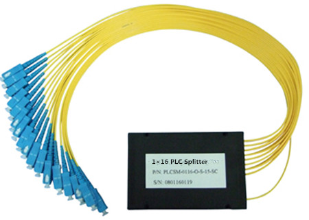
PLC splitter—A PLC splitter is a micro-optical component based on planar lightwave circuit technology and provides a low cost light distribution solution with small form factor and high reliability. It is manufactured using silica glass waveguide circuits that are aligned with a V-groove fiber array chip that uses ribbon fiber. Once everything is aligned and bonded, it is then packaged inside a miniature housing. PLC Splitter has high quality performance, such as low insertion loss, low PDL (Polarization Dependent Loss), high return loss and excellent uniformity over a wide wavelength range from 1260 nm to 1620 nm and have an operating temperature -40°C to +85°C. The following picture shows a PLC splitter connected with LC LC single mode patch cord.
PLC splitter
Advantages and Disadvantages of FBT and PLC splitters
1. FBT—Fused Biconical Splitter
FBT splitter is one of the most common splitters, which is widely accepted and used in passive networks. FBT splitter is designed for power splitting and tapping in telecommunication equipment, CATV network, and test equipment.
Advantages
  • The product is well-known and is easy to produce, thus reducing cost of production.
    Splitter ratios can be customized.
  • Can work on three different operating bands (850nm, 131 Onm, and 1550nm).
Disadvantages
  • Restricted to its operating wavelength.
  • Because of errors in equality insertion loss, the maximum insertion loss will vary depending on the split and increase substantially for those splits over 1:8.
  • Because an exact equal ratio cannot be ensured, transmission distance can be affected.
  • High temperature dependent loss (TDL). The operating temperature range is 23 °F- 167 °F. Any changes in temperature can affect the insertion loss.
  • The larger the split, the larger the encapsulation module.
  • Susceptible to failure due to extreme temperatures or improper handling.
2. PLC—Planar Lightwave Circuit Splitter
PLC splitter is a hot research at home and abroad today, with a good prospect of application, which is used to distribute or combine optical signals. It is based on planar lightwave circuit technology and provides a low cost light distribution solution with small form factor and high reliability.
Advantages
  • Suitable for multiple operating wavelengths (1260nm–1650nm); unstinted.
  • Equal splitter ratios for all branches.
  • Compact configuration; smaller size; small occupation space.
  • Good stability across all ratios.
  • High quality; low failure rate.
Disadvantages
  • Complicated production process.
  • Costlier than the FBT splitter in the smaller ratios.
Conclusion
Similar in size and outer appearance, PLC and FBT splitters provide data and video access for business and private customers, but internally the technologies behind these types vary, thus giving service providers a possibility to choose a more appropriate solution. FS.COM provides a full range of optical fiber splitters for you to choose from. If you are interested, you can have a look at it.