Showing posts with label LC to LC patch cord. Show all posts

Tuesday, September 20, 2016

Do You Have Any Idea of Water-Resistant Fiber Optic Cable?

There is no doubt that fiber optic cables play an integral role in telecommunication industry. Applications like data centers, local area networks, telecommunication networks, industrial Ethernet, and wireless network are all needing fiber optics to ensure smooth connectivity. Each application requires a specific cable design based on performance requirements, environmental conditions, and installation type. The common fiber optic cables like LC to LC patch cord cannot adapt to the harsh environment (e.g. moisture environment or underground deployment), thus water-resistant fiber optic cables are highly demanded on the market due to their water proof nature. Here is what you should know about the water-resistant fiber optic cable.
Overview of Water-resistant Fiber Optic Cables
Water-resistant fiber optic cable refers to the special type of fiber optic cable that are designed and specified for installations where the cable will come in contact with water or moisture, such as aerial, direct buried, or in conduit. The cables in these applications are exposed to or can be temporarily submerged in water, so they contain either a water-resistant gel-filled or gel-free (dry gel) polymer.
Generally, fiber optic cables can be divided into three types—outside plant cable (OSP), indoor/outdoor, and indoor, which are specified based on the environment and location where they are installed. With the exception of indoor cables, all cables contain water-resistant gel-filled or gel-free material to protect them from water and moisture. Before the use of gel-filled and gel-free materials, flooded core was another water-blocking method that is rarely used today (it has been replaced with gel-filled). The following image shows the gel-filled cables.
The gel is a gooey substance that must be removed when accessing and installing the cable. Gel-free cables, which are now more widely used, contain a super-absorbent polymer powder that is activated when it comes in contact with water or moisture. This blocks the water from penetrating the cable and allows for some expansion and contraction with temperature changes. Indoor cables do not contain water-resistant material since they are not typically exposed to water. Indoor (and indoor/outdoor) cables must meet additional flammability requirements dictated by local codes, such as the National Electrical Code.
Tight-Buffered & Loose Tube Cable Construction Provides Excellent Moisture Resistance
Water-resistant materials and cables are included in many industry specifications and standards. Generally, there are two basic water-resistant cable designs: Tight-buffer cables (primarily used inside buildings), Loose tube cables (used for OSP and indoor/outdoor).
It is known to all that most tight-buffered cable designs (seen in image below) are specified for indoor use, but some of them are designed with water-resistant powder and yarn, making them suitable for some indoor/outdoor applications. This tight-buffered cable utilizes an different design approach to deal with the moisture issue. Buffer materials are low-porosity plastics with excellent moisture resistance. This construction very effectively minimises the water molecule and OH-ion concentration level at the glass surface and virtually eliminates the stress corrosion phenomenon.

In loose tube cables (seen in image below), in order to prevent the water from reaching the 250μm coated fibers, the tubes surrounding the fibers must be filled with water-absorbent powder or gel that withstands high-moisture conditions, making them excellent for outside plant applications. This approach is especially made to waterproof the cable by filling the empty spaces in the cable with gel. The gel-filled tubes can also expand and contract with temperature changes, which makes loose-tube cable great for harsh, high-humidity environments where water or condensation can be a problem. However, gels can move, flow, and settle, leaves an uncertainty of the filled level of any particular point of a loose-tube gel-filled cable. Because loose-tube cable is typically 250 microns, you'll need a fan-out kit to build up the individual fiber strands to 900 microns when making the transition at the entrance point from outdoor loose-tube to indoor to tight-buffered cable.

The same level of protection remains in place all along the fiber, regardless of installation conditions, environment, or time. The balance of the tight-buffered, tight bound cable designs is such that it minimizes the open spaces available in the cable structure in which water can reside. Even if an outer cable jacket is cut, or water otherwise enters the cable structure, only a very small percentage of the cross-sectional area is open to water.
Conclusion
When selecting the suitable fiber optic cables, one must consider the application, the installation location, and the appropriate cable design and type according to specifications and standards. The water-resistant optic cable is specially made for moisture environment to insure the smooth connectivity. However, whether to have the loose tube fiber optic cable or tight buffered cable, it depends on the installation location. FS.COM offers a full range of fiber optic cables at very economical rates. These cables are widely used and are highly demanded on the market due to their water proof nature. In addition to this, we offer these cables in various fiber optic cable specifications, such as duplex/simplex fiber cable, single-mode/multimode fiber optic cable, LC/FC/SC/ST fiber optic cable and so on. LC to FC patch cord is absolutely high quality and low price, just as the other fiber optic cables. If you want to know more about our products, please contact us directly.

Tuesday, September 6, 2016

10G Data Center Cabling Solutions

The rapid development in data center throughput has led to the increasing usage and demand for higher-performance servers, storage and interconnects. And the old 1G Ethernet cannot handle the heavy-loaded solutions in data center any more. As a result, datacenter designers are looking to the expansion of higher speed Ethernet solutions, specifically 10 G and 40G Ethernet. As for 10GbE, there are two broad categories—SFP+ optical options and 10GBASE-T available on the market, which pose difficulty in selecting the appropriate 10-gigabit physical media. This article will make a brief introduction to these two 10G solutions to help you choose the suitable one.
What Is 10G SFP+?
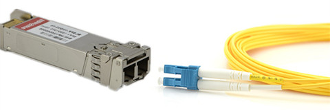
10G Small-form-factor pluggable plus (SFP+) is the industry standard for data rates up to 10 Gbps, which is also MSA compliant. SFP+ module is especially standardized for 10 Gbps application, and is identical in dimensions to the SFP. To achieve the SFP+ form factor reduction, only the optical-to-electrical and electrical-to-optical conversion functionalities occur inside the optical module. The key advantage of SFP+ over the existing 10 G optical interconnects is the higher port densities enabled by its dimensions, and lower power consumption. Figure 1 shows a SFP+ modules connected with a LC to LC patch cord.
10G-SFP-duplex-patch-cable
SFP+ transceivers are available in different 10G Ethernet standards—10GBASE-SR, 10GBASE-LR, 10GBASE-LRM, 10GBASE-ER, 10GBASE-ZR, 10GBASE-LX4 and 10GBASE-PR. Each standard has a unique specification that can be suitable for different applications. SFP+ optics are selected more often when designers need faster and more reliable solutions to handle 10 Gigabit Ethernet optical lines. With lower power usage and low latency, SFP+ ports are most commonly used for enterprise switches and also for plug-in cards for servers.
How Does 10G Copper Solutions Compare?
10G Ethernet can also run over twin-axial cabling, twisted pair cabling, and backplanes. SFP+ direct attach cable, 10GbASE-CX4 and 10GBASE-T are the common copper solutions for 10G short-reach interconnect. 10GBase-CX4 achieves the aggregate rate of 10 Gbps by transmitting over four independent cables at 3.125 Gbps. The disadvantage of this solution is the bulkiness of the cables that have eight twin-ax cables within them for a duplex link. And the bulkiness of the cables makes cable management more difficult. This becomes a significant limitation as the port densities and inter-port connection densities increase. Additionally, the number of conductors make these cables expensive compared to SFP+ cables.
10GBase-T enables 10 Gbps transmissions over Cat 6 and higher quality cables using complex signal processing and channel coding. The potential advantage of this technology is its extended reach. The extended reach and ability to enable structured cabling are not required for the short reach interconnects between servers and switches collocated in a rack. The disadvantages are its high power consumption and latency. The high latency in particular is a key limitation in latency sensitive data center and storage applications.
SFP+ Direct Attach DAC is another lower cost alternative to fiber with a limited link length of 7 meters. Additionally, it has significant power, cost, and performance advantages over the above media as explained below.
Why Use 10G DAC Cables in Data Center?
As 10 Gbps interconnects become ubiquitous in servers, providers are looking for a low cost, low power, and space efficient interconnect solution for the short reach (5-7m) links that dominate the data center environment. A length of seven meters covers all connections between server cards and switches, typically mounted on a single data center rack, and a vast majority of inter-rack connections. The SFP+ Direct Attach Copper is the 10G interconnect technology that matches these requirements, playing a vital role in enabling the next generation power and cost efficient data centers.
SFP+ Direct Attach Copper Solution
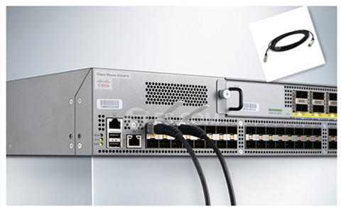
To further reduce cost and power in interconnect distances of 7 meters, which is sufficient to link server cards and switches, the SFP+ Direct Attach Copper replaces the optical modules and fiber with a passive copper cable with connectors identical to an SFP+ optical module. Figure 2 shows a SFP-H10GB-CU3M plugging in a Cisco switch. The reduction in cost and power are significant since the price of two optical modules required to support a full duplex link is approximately 10 times the cost of a fully connectorized SFP+ Direct Attach cable. In addition, the optical SFP+ modules consume around 1W each, adding 2W per port to the overall system power budget and cooling requirements.
DAC cable in a Cisco switch
Data is transmitted as 10 G serial NRZ (Non Return to Zero) symbols with transmit pre-emphasis and receive equalization compensating for Inter Symbol Interference caused by the board trace and the copper cable. This choice of serial NRZ transmission over a passive medium makes SFP+ copper both a low power and low latency solution compared to its alternatives.
Conclusion
As more emphasis is placed on energy efficient data centers and higher bandwidth applications, the need for a small form factor, low power, low latency and low cost interconnect makes SFP+ Direct Attach the optimal solution for short-reach 10G interconnects. While SFP+ fiber options provides a great path for higher performance long haul applications. FS.COM is a top manufacturer for DAC Twinax cables (SFP+ Cables, XFP Cables, CX4 Cables, Infiniband Cables, etc) and best suppliers for QSFP+ products including 10G & 40G QSFP+ copper and AOC cables. Optics transceivers like QSFP+, SFP, SFP+, XFP, X2, XENPAK, SDH, Bidi are also offered. If you have any interest in our products, you can contact us directly.

Thursday, August 18, 2016

Basic Information About Fiber Optic Cables

Nearly 40 years ago, fiber optic cable was made and installed, and it is still used today. Newer cables now being made are of even better quality. Compared to traditional copper wiring (commonly found in homes), fiber optic cables offer much higher data rates and are capable of reaching longer distances. This flexible and durable fiber is most commonly used to transmit light for a wide range of applications like visible light displays, sensors, and high-speed communications networks, which will be discuss in this article.
Fiber Optic Cables for High-Speed Applications
Although fiber optic cable is made of hair-thin glass or plastic to a desired length and diameter, inch for inch it’s stronger and steal and more durable than copper. For more detailed information about fiber vs copper, you can see a blog entitled “Why is the fiber optic technology better than copper?”. What’s more, there is no theoretical lifetime for optical fiber. And other key features of optical fiber are its electrical insulative properties, cost effectiveness, and improved security of the information being transmitted.
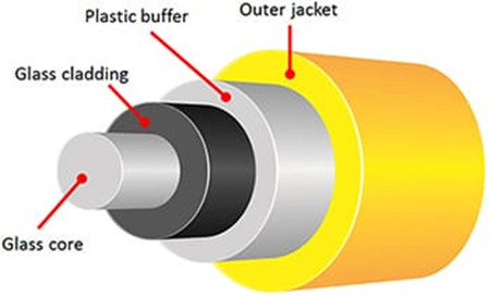
Fiber-optic-cable-structure
In terms of fiber optic cable construction, optical fibers have a transparent core which is surrounded by a transparent cladding material with a lower index of refraction, which helps to keep light in the core see in the above picture. Due to some leakage of light over a distance, attenuation is a result of the decrease in intensity of the light beam as it travels through the optical fiber. Attenuation is the most important limiting factor in the transmission of light signals (especially over long distances), although dispersion of the light is another factor that affects performance.
Single Mode and Multimode Fiber Optic Cables
Over the years, significant research and development has been invested into improving the general performance of fiber. Most are continuously improved upon to further minimize attenuation/loss and dispersion over longer distances and there are many subsets that apply to very specific network and performance standards. However, the two primary categories are single mode and multimode optical fibers.
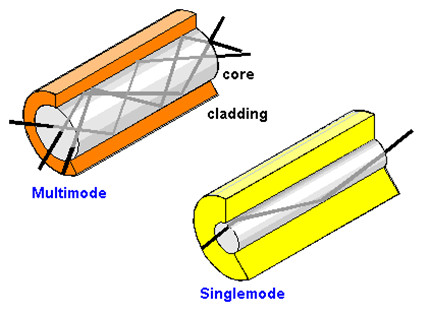
Single mode fiber patch cables have a smaller diameter core (9µm) that only allows for one mode of light to propagate. As a result, the amount of light leakage decreases and minimizes the attenuation, allowing the signal to travel longer distances. Typically, single mode fiber is used for distances beyond several hundred meters by telecom and CATV service providers, government agencies, and major enterprises and universities with large campuses and networks.
single mode and multimode fiber cables
Multimode optical fibers have a larger diameter core (50µm or 62.5µm) than single mode fibers, which allows for the propagation of multiple modes of light. The amount of light that passes through the core is increased, thus enabling a higher amoutn of information to pass through at any one time. Because of the higher rates of dispersion and attenuation, the signal quality is significantly reduced over longer distances, so multimode fibers are typically deployed for short distance applications within data centers, Local Area Networks (LAN) and other similar networks. Similar to single mode and other communication fibers, subsets of mutimode fiber types exist on the basis of construction/makeup (step-index, graded-index, etc) and for varying bandwidth rates over specific distances (OM2, OM3, OM4).
FS.COM Fiber Optics
Besides the single mode and multimode fiber optic cables, there are many standard and specialty for fiber optic cables existed for use within communications networks. For high-speed networking services, fiber optic network offers much higher internet speed and supports longer transmission distance, which makes it the clear choice for what’s now and what’s next.
Fiber optics FS.COM
FS.COM has been providing custom lengths of optical fiber to all of our customers for network simulation, latency, and system demonstration applications. All of our high-quality fiber cable assemblies such as Patch Cords, Pigtails, MCPs, Breakout Cables are ordered at lower price. Additionally, fiber optic cables are also divided by different connectors like LC to LC patch cord, ST-LC patch cord, SC to LC patch cable and so on. If you have any interest of our products, you can contact our experienced team for a free consultation.

Thursday, June 30, 2016

Guide to Fiber Optical Connectors

Fiber optical cable is the composite material, typically consists of a hair-thin glass used to transmit pulses of light instead of electrical signals. Thus the termination must be much more precise. Compared with copper cables end with RJ connectors, fiber optic connectors must align microscopic glass fibers perfectly to make metal to metal contact. There are many different types of fiber connectors, they share similar design characteristics, such as LC to LC patch cord, single mode LC to ST fiber patch cable, single mode fiber ST to SC patch cord, single mode fiber cable with LC connector, etc. Nowadays most cables are ended with the same connector, which poses a problem for users to sort through cables and connectivity options. That’s why this article is provided here to help out the illustration of fiber optics and optical connectors.
fiber-optic-connector
Internal Structure of Optical Connector
Fiber optic connector terminates the end of fiber optic cable, enabling quicker connection and disconnection than splicing. As noted before, optical connector has to be aligned properly to the microscopic glass fibers completely in order to allocate for communication. There are three major components of a fiber connector: the ferrule, the connector body, and the coupling mechanism.
  • Ferrule
It is a thin structure that is actually used to holds the glass fiber, which has a hollowed-out center that forms a tight grip on the fiber. Ferrules are usually made from ceramic, metal, or high-quality plastic, and typically will hold one strand of fiber.
  • Connector Body
This is a plastic or metal structure that holds the ferrule and attaches to the jacket and strengthens members of the fiber cable itself.
  • Coupling Mechanism
This is a part of the connector body that holds the connector in place when it gets attached to another device. It may be a latch clip, a bayonet-style nut, or similar device.
Different Types of Fiber Optic Connectors
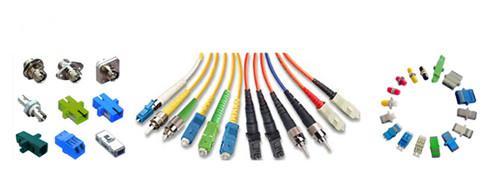
To sum up, there are nearly 100 fiber optic connectors on the market, but only a few are available that was lower loss, lower cost, easier to terminate. Optical connectors like LC connector, SC connector, ST connector, FC connector, RJ45 connector, MT-RJ connector are the representative that will be present to you.
  • SC Connector
SC
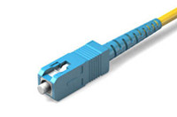
SC or square connector, was developed by Nippon Telegraph and Telephone on the market, slowly grew in popularity as manufacturing cost went down. Now it is becoming increasingly popular in single-mode fiber optic cable, analog CATV, GPON, GBIC. SC is a snap (push-pull coupling) connector with a 2.5mm ferrule diameter that operates on the standard IEC 61754-4. The connector’s outer square profile together with its snap coupling mechanism that allows greater connector packaging density in instruments and patch panels. The SC fiber patch cord is ideally suited for datacoms and telecoms applications including point to point and passive optical networking.

  • LC  Connector
LC
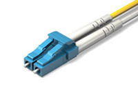
LC or Lucent Connector, is a push-pull, small form factor connector that uses a 1.25mm ferrule, half the size of the SC. Due to the combination of small size and latch feature, LC connector is ideal for high-density connections and usually utilized in SFP, SFP+, XFP, and single-mode QSFP+ transceivers. Along with the development of LC compatible transceivers and active networking components, it will continue to grow in the FTTH arena.


  • FC Connector
FC
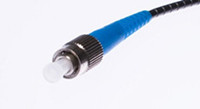
FC or Ferrule Connector., is a round, threaded fiber optic connector that was designed by Nippon Telephone and Telegraph in Japan. The FC connector is applied for single-mode fiber and polarization-maintaining optic fiber. The FC is a screw type connector with a 2.5mm ferrule, which was the first fiber optic connector to use a ceramic ferrule. However, FC is becoming less common and gradually replaced by SC and LC connectors because of its vibration loosening and insertion loss.

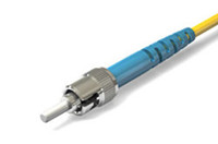
  • ST Connector
ST
ST or Straight Tip, was developed by AT&T shortly after the arrival of the FC. They may be mistaken for one another, but ST uses a bayonet mount other than a screw thread. And you have to make sure SC connectors are seated properly owing to its spring-loaded structure. SC is mainly used in multimode fiber optic cable, campuses and buildings.


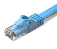
  • RJ-45 Connector
RJ45
RJ-45 connectors are physically wider than the RJ-11/12 connectors used for telephone. In network applications, RJ-45 cable assemblies are used to connect from a patch panel to a network switch, and also to connect a computer's NIC to a data port.


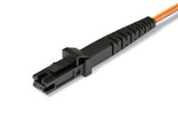
  • MT-RJ Connector
MJRJ
The MTRJ connector closely resembles an RJ-style modular plug, even getting part of its name from the resemblance. It is covered in the TIA connector intermateability standard FOCIS-12 (TIA-604-12). MT-RJ is a duplex connector with both fibers in a single polymer ferrule. It uses pins for alignment and has male and female versions. Multimode only, field terminated only by prepolished/splice method.


Conclusion
Whether you are about to install a new fiber optic network, or perhaps you are maintaining on an existing one, you are supposed to have a basic knowledge about fiber optics and optical connector. This article simply illustrates the most commonly used fiber optic connectors on the market to help you sort through the optical connectors. But if you’re still not sure which fiber optic connectors are right for you, or perhaps you’d like some more information you can always get in touch with FS.COM.