Showing posts with label fiber optic cable. Show all posts

Thursday, August 3, 2017

OM5 Fiber Cable – Is It Worthwhile for 40G/100G SWDM4 Cabling Solution

OM5 multimode fiber, as the advanced version of the old OM4 fiber, is thought to be the future of multimode cabling. It is the Wideband multimode fiber (WBMMF) that can support wavelengths between 850nm and 953nm. It is also designed to support the short wavelength division multiplexing (SWDM)—one of the new technology for 40G/100G connection. However, will it be the ideal transmission medium for 40GbE/100GbE cabling solution?
How OM5 Fiber Developed
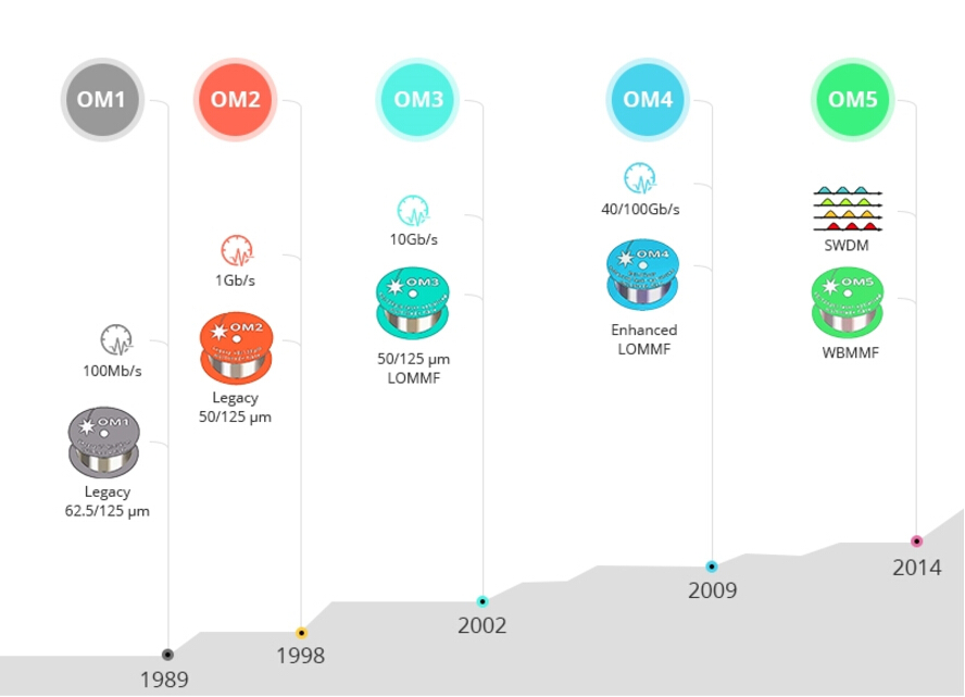
Over the past thirty years, multimode fiber has been evolved from OM1 to OM5 multimode fiber. OM1 and OM2 fiber, released at the end of 20th century, are the legacy 125µm multimode fiber that are working fine in 10Mb/s, 100Mb/s and 1000Mb/s cabling solution. However, with the high speed data rate like 10Gb/s, 40Gb/s, 100Gb/s and beyond coming into our life, multimode cabling (OM1 and OM2 ) with LEDs can not meet the requirement. The laser-optimized OM3 and OM4 has been developed subsequently. OM4 fiber cable, with the internal construction, possess higher modal bandwidth than OM3 fiber, which is commonly used fiber medium for 40G/100G connection.
OM1-OM5 fiber
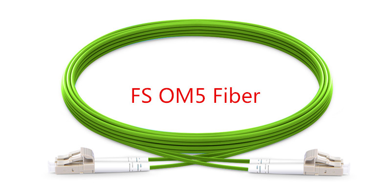
But there is a problem. In a 40G layout, fiber optic technicians have to use one MTP fiber and 4 OM4 duplex fibers (total 8 fibers), which is obvious not preferable for high-density cabling networks. So here comes the OM5 fiber. By utilizing SWDM technology, it can greatly reduce fiber count into 2 fibers (4×10G) in 40G networks, 2 fibers (4×25G) in 100G links. OM5 is the lime green multimode fiber, displayed as follows.
OM5 Fiber
OM5 Fiber for 40G/100G SWDM4 Cabling Solution
Reduce fiber count for 40G/100G connection—OM5 fiber as the advanced version of OM3/OM4 fiber, is backward compatible with OM3 and OM4 fiber cabling. And with the SWDM technology, this fiber can only use two OM5 fibers and 40/100G SWDM4 transceivers in 40G and 100G SWDM4 cabling.
Longer-transmission distance—OM5 is designed and specified to support at least four WDM channels at a minimum speed of 28Gbps per channel through the 850-953 window. Compared to OM4 fiber cable, it is specified only to work at the 850 nm window. OM5 multimode fiber delivers higher value to network owners for distances up to 440m (for data rates up to 40Gbps), and allows for smooth migration to 400Gbps for distances up to 150m. While OM4 fiber cover the distance of 350m, 100m over 40G/100G respectively.
Easy management & installation—in 40G/100G network, multimode connectivity together with MTP/MPO systems makes for a more user-friendly solution for data centers as well as building and campus backbones, especially in cable installation, troubleshooting, cleaning, and overall maintenance.
FS OM5 Cable Solution
FS offer Lime green OM5 fibers. All our OM5 fiber cables are guaranteed by End Face Geometry Test, Continuity Test, and 3D interferometry Test to be high quality. Available in LC, SC, FC, ST, etc. Connectors, and the cable length of OM5 fiber can be provided from less than 1 meter to more than 100 meters, which will well meet the needs for 400m transmission of 40G SWDM4 QSFP+ module and 100m transmission of 100G SWDM4 QSFP28 module, as well as the links on the same rack or row.
fiber optic cable
Not only the OM1/OM2/OM3/OM4/OM5 multimode fibers are provided at FS.COM, but fiber optic cables like singlemode fibers (OS1/OS2) , Twinax copper cables are also offered. For more information about the cost-effective fiber patch cables, Please feel free to contact us via www.fs.com.

Monday, December 5, 2016

Do You Know How Fast Your Fiber Optic Internet Can Be?

It is no secret that the technology is continually evolving, so does the demand for consistent and accessible information and entertainment. From the old 56 kbqs crawl of dial-up, to the early 1 Mbqs copper connections and all the way to the existing popular 1 Gbqs, 10 Gbqs/40 Gbqs fiber optic connections, we’ve gone through a drastic improvement to maintain a stronger signal, a better connection, a faster speed. It seems that the intricacies of internet can get complicated, so how do you draw the line with your internet consumption and speed demands? So in this blog post, we explain how fiber optic works, why cause the boom in fiber optic speed and how fast fiber optic internet can be.
How Does an Fiber Glass Function in the Internet?
We know that fiber optic cable works like a bridge between the consumer and internet supplier. But how does this process actually work? To put it simply, fiber cable works by sending data as pulses of light through a glass fiber. At one end of the fiber, a laser or LED transmits data as light. At the other end of the cable, the light will be interpreted into data by the light-sensitive receptors.
If the above explanation is not clear to you, then here comes the more vivid description. Fiber optic cables consists of a strand of fiber glass wrapped in a protective jacket called cladding. Owing to the total internal reflection, light can go from one end of the core to the other end without ever changing its wavelength. More detailed information, please see an article entitled “A Quick Lesson In Fiber Optics”.
Fiber Optic Cable Types: Single-mode and Multimode Fiber
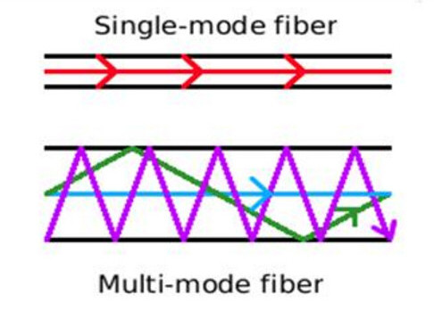
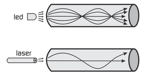
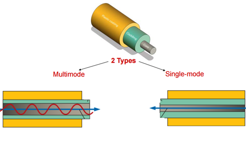
Single-mode and multimode fibers are the two broad categories of fiber core that can affect how light can travel through the cable. In single-mode fiber optic system, there is only one pathway or mode that light can travel along. While in multimode fiber optic system, seen in the below image, there are multiple pathways just like a circus funhouse with beams of light traveling along a variety of pathways through the core.
single-mode-and-multimode-fiber
Theoretical, if you have one light beam traveling in both the single-mode and multimode fibers, the straight line beam of the single-mode fibers will reach its destination first. This difference is usually caused by the modal dispersion, which explain the reason why we often use the single-mode fibers for longer reach application.
WDM and Dark Fibers
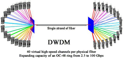
The advent of WDM (wavelength division multiplexing) in the mod-2000s as a great breakthrough in fiber optics as it allows multiple channels to be carried at the same tine on a single fiber optic cable. There are all together CWDM and DWDM systems, CWDM or course WDM is the initial implement that allows 4 and 8 wavelengths, such as the Ethernet LX-4 standard which allowed a cable to carry four 3.125 Gbit/s data channels, resulting in 10Gbit/s aggregate.
In DWDM (Dense WDM) system, even though it is much more expensive, it can handle up to 160 data channels expanding basic a 10 Gbit/s system over a single fiber pair to over 1.6 Tbit/s.
dwdm
Figure 2 display different wavelengths can be bundled together in the same mode.
In terms of the new concept—dark fiber, it represents the unused cable laid in the network as space capacity, carrying high amounts of data at high speeds over hundreds of miles. Simply put, with DWDM, dark fiber network can easily increase bandwidth and allow more data to be send via optical fibers. And as the price reduces, dark fibers are gradually becoming more popular than ever.
How Do You Find out What Speed You Need?
This seems to be a noob question. As you can simply use the speed testing websites to discover the speed of your internet connection. And tracking the aspects of your internet use can give a better ideal of what speed you have and the speed that is optimal for you. What I want to express here is the common mistakes you will make.
It is not always the ISP’s fault, if your speeds are slower than what you expect. Several factors might have great impact on the accuracy of speeds. For example, the types of the hardware you have, the age/types of the line you have, and how busy the internet is at all time.
To find what speed you need depends on several different elements. How you plan to use the Internet, how many devices you have in your home, and how fast you expect to be connected are just a few factors that influence which speed is right for you. For office network, network speed under gigabit Ethernet is not sufficient.
Remember, speed is a maximum level, not a guaranteed one. As your desire for a faster connection increases, be sure you have the Internet speed that will exceed your technological needs!
The Next Steps for Fiber Optics
The modern commercial fiber optic system enjoys it stay in the Gigabit Ethernet speed. But we can look forward to the increases in the range of gigabits per second down speed, perhaps even breaking into the terabit range, in the not so distant future.

Tuesday, November 22, 2016

How Far Can You Bend Your Fiber?

We know that stress and overstrain is a major enemy of the fiber’s lifespan, so cable installers must ensure that during the installation, fiber cables would not suffer from undesirable stretching or bending. Pulling, pushing and blowing are the three techniques used in wire management, which usually cause minor installation strains even for a seasoned installer. It is unavoidable, but fiber optic cables made of glasses have a limitation of bending ratio or tight diameter. If it do not exceed the certain diameter, the fiber will function well. Therefore it is essential for us to know how far cables can be bent. In fact, the maximum transmission distance of the fiber optic cable depends on the aspects like bend radius, tensile strength and usable duct space, which will be clearer illustrated in the following article.
Bend Radius
Bend radius is the curvature an optical fiber can bend without damage or shortening its lifespan via kinking. The smaller the rated bend radius, the more flexible the fiber. Just check the manufacturer’s spec for bend radius before purchasing the products. If no recommendations are available from the cable manufacturer, the cable should not be pulled into a bend radius smaller than twenty times the cable diameter. For example, a cable with an outer diameter of 5 mm, should not be bent smaller than 100mm radius during installation.
Maintaining proper bend radius is key in preventing service calls due to damage and signal loss in your optical fiber. Bend loss usually occurs when the fiber cable bends is tighter than the cable’s maximum bend tolerance, which might damage the fiber by causing micro cracks.
There are a couple of factors that may mitigate the problems of bend radius and the angles within them. If a fiber cable is being pulled or pushed through an empty duct or mini-duct, obviously there is less resistance to the cable and you can pull/push greater distances. If the coating of the outside of the cable and the inside of the duct are designed to reduce friction, you will be able to achieve greater distances as well.
bend-sensitive-cable
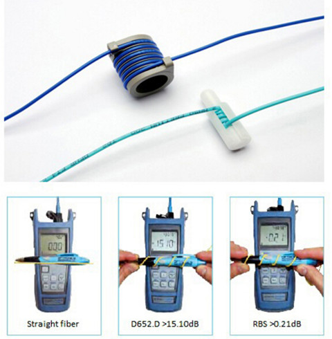
With well-designed bend insensitive fiber patch cables (seen in the above image), you can usually push a fiber cable as far as 90 degree angles in the run with minimized signal loss compared with the traditional fiber patch cables.
Tensile Strength
Just as the bend radius, fiber optic cables also have a maximum tensile strength. If the cable is being pulled through, it is better not to exceed the maximum tensile load. However, if the cable is being installed within a microduct or conduit, pushing the cable will apply no tensile force.
Over-stressing the fibers will not be noticeable until after installation since the cable outer sheath will elongate, whereas glass optical fiber will not. Ideally, a breakaway swivel should be used, however, where this is not possible, the installation crews should use a tension gauge attached to the pull-cord. As a rough approximation, 100 Newtons is equivalent to a 22lbf (pounds-force) load applied directly to the cable.
Usable Duct Space
The full space in the duct is not usable for cables because of horizontal and vertical bends and joints. Usable duct space should be at least 60%. 900µm and 250µm fibers are basically two kinds of fiber patch cables. 900µm fibers can easily be damaged with respect to the storage and wire management. 900 µm kinks easily, but is very flexible and installs easily. Sometimes, you have to balance ease of installation with toughness. The difference between 250um Loose-tube and 900um Tight Buffered Fiber have illustrated in the above article.
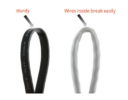
During the cable installation, you must get the fiber through walls—possibly in basements, attics, or crawl spaces, and then through floors, walls and, eventually, through a room to the CPE location. For rugged spaces where your fiber may suffer damage, such as basements or in conduits sharing space with electrical or other wiring, you may need a 3mm rugged sheathed cable that is flexible and crush resistant. The image below shows fiber optic cables being kinked. The flat cat5e cables (left) and common Ethernet cable (right) have different effect after bending.
flat-cable-and-common-ethernet-cable
Therefore, a good rule of thumb to use in planning your fiber drop is below: Bends (angles) = Friction—maximum distance of the pushable fiber
In addition to the above bend radius, here are some other areas to focus on to achieve maximum distance without damaging the cable: signal power and performance requirements for each device or revenue generating unit, locations of required splices, list of cable lengths required. When using duct or cable in conduit, keep in mind that freezing water in the conduit can crush the cable—and it may be wise to use microduct.
Summary
One of the challenges of installing fiber is to choose a cable with a very small bend radius, and it is tough enough to handle many different installation conditions. Once you have selected the appropriate fiber, plan your route to minimize bends and friction. By planning ahead and thinking carefully, you can save money by reducing the costs of those services. FS.COM, as a professional telecom vendor, offers a full range of cable management components, like the patch panels, cable manager & wire duct, fiber enclosures and so on. Some special cables including the bend insensitive fiber patch cables, flat fiber optic cables are also offered. If you have any interest, please send your request to us.

Thursday, October 20, 2016

How to Organize the Colorful Cables in Your Rack

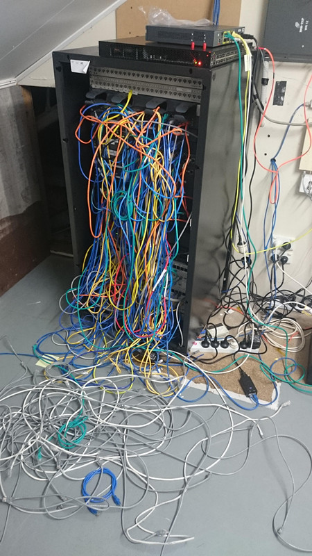
Network designers may encounter a problem when they are about to organize the spaghetti-hell cables in the rack (seen in the below image). They don't know where to start. So how do you organize the cables in your racks? What method do you use for the re-installation? Do you use any tracking software or physically label the cables? How to label the cables? In fact, it is essential for data center infrastructure to well organize all the cables in the racks. It not only helps users install and route cables in an easier and more accurate way, but reduce the time required for further maintenance. Therefore, this article will provide two identify methods to help you out.
cable-spaghetti
Label Each Cable and Panel
Labeling system can clearly identify all components of the structured cabling system including racks, cables, panels and outlets. If you don't label your cables, you're only making more work for yourself. Every cable should have a label on both ends, even short runs and patch cables. Only in this way, you will know where each cable goes when you unplug a few patch cables for a switch, and reset them back to their default locations.
There are two methods that you can use to label your cables with a generic labeler. You can run the label along the cable, so that it can be read easily, or you can wrap it around the cable so that it meets itself and looks like a tag. The former is easier to read, the latter is either harder to read or uses twice as much label since you type the word twice to make sure it's read. Long labels on mine get the "along the cable" treatment, and shorter ones get the tag.
Use Color Coding for Quick Visual Identification
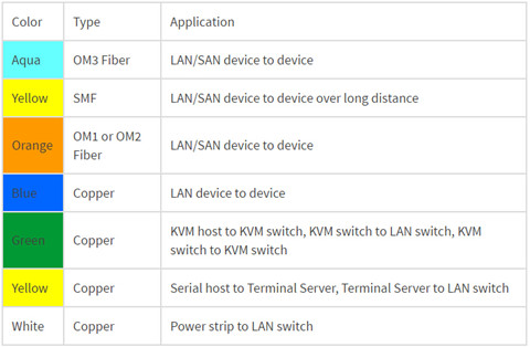
Color coding can be a solution to the problem of wire identification, making locating cables from a distance easier. Users should use a specific color cable for a specific purpose so that they can easily and rapidly trace cables back. And one thing you are supposed to bear in mind is that never use colors randomly. Make sure each color has a purpose and stay with it. That will make it easier to follow cable runs and troubleshoot issues. And it also makes for a better-looking data center. The below image shows the example color scheme for patch cables.
color-scheme
Note: the color scheme depends on the cable manufacturer and your color coding plan. If you use colors to identify cable functions or connections, be sure to build in redundancy to accommodate individuals with color blindness or color vision deficiency.
Hints About Color-Coding and Labeling
  • Visually identifying cables will save you time tracking them down.
  • Use color and labels to identify and organize: cables’ role and function or connection type, dual-power feeds for redundant power sources.
  • Use secure labels that can be seen but difficult to remove.
  • Maintain a spreadsheet that identifies the cables and colors, where cables come from and go, and configurations.
Summary
There is no need to mention the importance of cable identification. Once you begin to identify the cables in your racks (whether to use color coding or labeling), please hold on to it. Or you'll confuse yourself and those who work for you. In all, use of the color coding or labels is the best practice to identify cables in a rack. FS.COM offers a full range of fiber optic cables such as single-mode fiber, multimode fiber (OM1/OM2/OM3/OM4), simplex and duxplex cables, Ethernet cables (cat5e/6/7), etc. Besides, Cable Wire Markers and Cable labels & Printers are also offered. If you have any requirement, please send your request to us.

Tuesday, October 18, 2016

The Benefit and Challenge of Patch Panel

Patch panel is undoubtedly an essential component in cabling systems as it provide a simple, neat and easy-to-manage solution. For example, if you want to wire a network system that includes multiple wall ports, patch panels will not only allow you to terminate cable elements, but the signal to be connected to the final destination. No matter how big or small your business infrastructure is, patch panel is indispensable. So what is a patch panel? What are the exact benefits of using fiber optic patch panel? This article will provide some detailed information about the benefits and challenges of them.
What Is A Patch Panel?
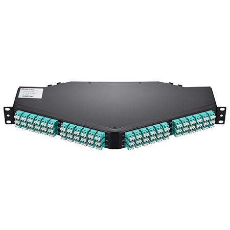
A patch panel is, in fact, an array of ports on one panel used to connect and manage incoming and outgoing LAN cables. The following image shows a 128 fibers MTP to LC/UPC OM4 1U 40GB QSFP+ Breakout Patch Panel. Each ports of patch panels connect fiber jumper cables to another port located elsewhere in your building. Circuits in an enterprise network can be easily rearranged by plugging and unplugging respective patch cords. Furthermore, patch panel provides a single location for all input jacks, which greatly simplifies the troubleshooting problems.
128-fibers-mtp-to-lc-om4-1u-40gb-qsfp-breakout-patch-panel
Patch panels are usually attached to network racks, either above or below network switches and take up 1U or 1.75 inches of space. Patch cords connect the ports in the patch panel to ports in the network switch, which creates permanent port connections to the switch that won't be interrupted during moves, adds and changes (MACs). Based on different standards, there are different types of patch panels. For instance, 48-port, 24-port and 12-port patch panels divided by the number of ports, or the more specific patch panels—Cat 5E, Cat 6, Cat 6A and Cat 7 cables. Since you have a basic understanding of patch panels, let’s move on the the next part.
The Benefit
A patch panel performs no other function except for acting as a connector, but it does offer a range of benefits:
  • Use Standard Fiber Optic Cords
Since patch panel uses fiber optic cable to create interconnection, network designers can make changes and repairs without the delays and added expense associated with custom cabling.
  • Flexibility and Scalability
The network can grow and change on-demand, without the costly, labor-intensive hassle of replacing channels end-to-end.
  • Reduce Cable Congestion
Reduced cable slack means less clutter, less confusion and an easily organized, better-labeled cabling infrastructure. You can also manage cables in any direction–horizontal or vertical, front or back.
  • Space Saving
By managing varying port densities and speeds in a single high-density patch panel, you save valuable rack space, helping to lower data center costs. A single patch panel can manage as many as (168) 10 Gb ports.
  • Cost-Effectiveness
High-density and easy maintenance provide a low initial investment cost. With a patch panel, you can only buy the devices you need now, while leaving room for future expansion.
  • Ease of maintenance
The advantage of using a patch panel is that it allows manual monitoring, testing, switching, routing, and other maintenance to be handled quickly because the cables in the front that connect to the more permanent cables in the back are configured and made so that changes can be made quickly and easily when needed.
The Challenge
With several patch panels available for sale, network users usually feel puzzled to select a patch panel solution with the features and capacity to meet their current needs, as well as the flexibility and scalability to adapt to and grow with the future needs. As noted before, patch panels can be divided into several types. According to different cable type, there are copper and fiber patch panels, which will be introduced in the next part.
Copper or Fiber Patch Panel?
A Patch panel can be connected with either fiber or copper cabling. The primary role of fiber patch panel is to direct signal at a required speed. It is the common sense that fiber is much faster than copper, and fiber patch panels are more expensive.
Structurally, copper panels have the 110-insulation displacement connector style on one side and 8-pin modular ports on the other. Wires coming into the panel are therefore terminated to the insulation displacement connector. On the opposite side, the 8-pin modular connector plugs into the port which corresponds to the terminated wires. With the copper panel, each pair of wires has an independent port. The following image shows the 48 Ports Shielded(STP) Cat6 Feed-Through 2U Gigabit Ethernet Patch Panel.
48-ports-shieldedstp-cat6-feed-through-2u-19-gigabit-ethernet-patch-panel
Fiber panels require two ports for a pair of wires. One port serves the transmitting end while the other handles the receiving end. While fiber panels tend to be faster than copper, this does not downplay the role played by the latter. And if there are more than one type of the fiber optic connector used in the network, patch panels with hybrid adapters are necessary. These adapters can then be used to plug individual fibers into other devices. The adapters on a fiber optical patch panel can come in a variety of different shapes.
Conclusion
To sum up, the patch panels make it easy to organize the fibers in an business or home network. What’s more, working with the fibers within the tray of the fiber optical patch panel protects the fibers from anything in the environment that could damage them. You can choose all range of fiber optical patch panel from FS.COM with high quality and competitive price. If you have interest, feel free to contact us.

Sunday, September 18, 2016

Understanding Industrial Fiber Optic Cable

Fiber optic cabling usually utilizes ruggedized jackets to ensure optimal performance in the face of extreme temperatures; exposure to UV/sunlight, oil, and solvents; and crushing impact, which makes it the ideal solution in any industrial environment where high-speed, high-bandwidth data solutions are needed. It can be used for campus and in-building data backbones to anchor an operation’s Ethernet, and also for point-to-point digital signal transmission. Today’s article will make a brief introduction to the basics of industrial fiber optic cable.
fiber-optics-fs-com
The Advantages of Fiber Optic Cable
Compared to the conventional copper wires, fiber optic cables are smaller and lighter than copper cables, extremely durable and intrinsically safe, with no risk of spark hazards. In addition, the following part lists several detailed information about the benefits of fiber optics.
  • Higher carrying capacity—as the fiber optic cables are thinner than copper cables, more fibers can be bundled into a given-diameter cable. This allows more data information will be be carried across the network without interruption.
  • Less signal degradation—it is known that the loss of signal in optical fiber is less than in copper wire.
  • Lightweight—An optical cable weighs less than a comparable copper wire cable. Fiber-optic cables take up less space in the ground.
  • Flexible—Because fiber optics are so flexible and can transmit and receive light, they are used in many flexible digital applications.
Types of Fiber Optic Cables
Fiber optic cabling can be segmented based on design criteria and installation environment:
Loose tube cables lay thinly coated fiber strands into unitized thermoplastic tubes, giving the fiber strands flexibility to move within the tubes and the cable, which makes it possess the ability to stand up to outdoor temperatures and harsh environments. Although loose-tube gel-filled fiber optic cables are used for high-fiber-count, long-distance telco applications, they are an inferior design for the Local Area Network applications where reliability, attenuation stability over a wide temperature range and low installed cost are the priorities.
loose-tube-or-tight-buffered-cable
Tight buffered cables contain an individual buffer on each fiber stand, allowing for easy handling and quick termination. For common small fiber counts, this design delivers a smaller cable diameter than loose tube cables and is best suited for indoor environments. The most common designs for tight buffered cabling are distribution and breakout. For applications like moderate distance transmission for telecom local loop, LAN, SAN, and point-to-point links in cities, buildings, factories, office parks and on campuses. Tight-buffered cables offer the flexibility, direct connectability and design versatility necessary to satisfy the diverse requirements existing in high performance fiber optic applications.
Singlemode and multi-mode cables are another common types of fiber optic cables. Single-mode fiber strands are designed to interface with laser optic light sources for distances beyond 300 meters, while multi-mode strands or MM fiber patch cords are designed to interface with LED and vertical-cavity surface emitting laser (VCSEL) light sources for short-distance cabling runs.
Considerations When Installing Fiber Optic Cables
If you are considering using fiber optic cables in your installation, take a moment to review the installation guides. Firstly, for industrial installations, it is critical to consider and evaluate the environment. Additionally, as the fiber optic cables are more susceptible to damage during the stress of installation, therefore there are two specifications for bend radii—Bend Radii before installation and Bend Radii after installation. All hardware and support structures should follow the recommendations of TIA-569 and NECA/BICSI 568 Standards documents. Last but not the least, use cable management straps or cable ties to support cable bundles. Make sure these implements are fastened snugly, but not tightly around cable bundles.
Conclusion
There is without saying that the advent of fiber optic cable solutions has been one of the best things to happen to technology in recent years. With the demand on technology ever-increasing, fiber optic cables are becoming the preferred method of transmission over traditional coaxial solutions. FS.COM offers a full range of optical devices, such as fiber optic cable, optical transceivers, DAC/AOC cables and so on. Fiber patch cables LC to LC and LC LC single mode patch cord are provided with high quality and low price. If you have any requirement, please send your request to us.

Tuesday, July 19, 2016

10 Frequently Asked Questions About Fiber Optics

Fiber optical technology typically presumes a service life of nearly 30 years. It is not a revolutionary or a new technology, in fact it is only about carrying light from one point to another. The questions that frequently asked around the industry are the art of mysticism, thus this post has collected questions made by professional during seminars, forum and projects. Solutions are also provided respectively to help readers to form the general understanding of this system.
FS.COM
Do signals really travel faster in fiber optics?
The speed here doesn’t refer to the the speed of signals in fiber optic cable, but the bandwidth potential of the fiber. Because you know that the speed of light in glass is about 2/3 C, but you might be surprised to know that signals in UTP (unshielded twisted pair) cables like Cat 5e travel at about the same speed (2/3 C). Coax, meanwhile, has a faster NVP (nominal velocity of propogation), about 0.9C, due to it's design.
What do I need for connecting Optic Fiber Cable to a Cat 5 Cable?
You need a media converter available from a number of companies for nearly $100-200.
Do you see any real serious problems in splicing together fiber cables from different manufacturers, as long as the cable is manufactured to the same specifications?
No, not as long as they are the same type and size, for example, multimode 62.5/125 or 50/125 and single mode should be normal (non-dispersion shifted) or dispersion shifted. Some single mode fibers are made for 1300 nm only, 1550 nm only or both, and they should not be mixed. Note that there are some other single mode fibers that have special coatings that cannot be mixed with others. Therefore you are supposed to ask your fiber vendors, splicer supplier or try it first before going into the field!
Will a single mode connector work on multi-mode cable?
The answer is maybe you can use SM connectors on MM but not the reverse. SM connectors are made to tighter tolerances—as is SM fiber—so the ferrule hole may be too small for some MM fibers. MM connectors have bigger holes for the fiber and will have high loss (>1dB) with SM. Also MM connectors may not be PC (physical contact) polish - terrible for return loss. MM fiber may not fit the smaller hole in SM connectors.
If you have a 50 micron fiber backbone, can you use 62.5 fiber jumpers on each end?
NO! On the receiver end it is OK, but on the transmitter end, the larger core of 62.5 into smaller 50 micron fiber will have fiber losses of 2-4 dB.
What is your view on using fiber optic connectors? Is it a better terminating method than fusion splice?
Of all the SFF (small form factor connectors), LC connector is the one that has become the most popular. In fact, it is the de facto standard connector for gigabit and 10 gigabit networks. Indeed the design is very well thought out. The smaller ferrule of a LC to LC fiber cable is easy to polish well and has excellent mating performance—which leads to low loss and back reflection. It is also easy to terminante and test.
What is the theoretical lifetime of optical fiber and optical fiber cables?
There is no “theoretical lifetime” of optical fibers. There is no industry accepted “wear out” mechanism for optical fiber. So there is no physical-chemical reach to test and accelerate in order to predict an eventual failure mechanism and corresponding failure reaction rate.
Can the same fiber-optic transceivers that are used with Om3 fiber, like SFP+ pluggable modules, be used with Om4 fiber or are there new transceiver types that need to be used?
Yes, you can use the same fiber optic transceivers for both Om3 and Om4 fibers because the two fiber types are basically the same except that Om4 fiber has higher bandwidth. The IEEE 10G Ethernet standard states that 300-meter Om3 and 400-meter Om4 link lengths are supported with 10GBase-S-compliant transceivers.
Which cabling media are typically used in data center/storage area network (SAN) environments?
There are a variety of different types of cabling media deployed in the data center. Multimode and single mode fiber, direct attach connection (DAC) cables, CX4 copper cables, and Category 6A twisted-pair all have a place.
The cabling type that is deployed is typically based on port type, cost, and distance. Distance is dictated by the architecture of the data center, which can be centralized/direct connect, distribution/top-of-rack switching, zoned distribution, or a combination of these.
Fiber is often deployed to connect top-of-rack switches to an aggregation switch at the end of the row or in another location, in centralized architectures for the "home runs," and in zoned distribution architectures. Multimode fiber supports all distances in the typical data center, such as connecting top-of-rack switches within rows back to an aggregation or core layer, or connecting servers to end-of-row switches. For larger data centers, where MM fiber patch cords may not suffice, single mode fiber can enable much longer distances. Single mode fiber can also be deployed within the row as a strategy for future applications that might use multiple-wavelength technologies. Another alternative to traditional cable and connector deployments for connectivity between servers and switches within the rack is to use direct attached cables connecting to SFP+ ports.
Is fiber more difficult to install than copper?
It depends on the comfort level and training of the technicians. Because fiber has been accepted as the standard choice for communications backbones for many years, today's installers are generally comfortable with the technology, but there is a learning curve for those just starting out. Of course, the same could be said of new generations of copper cabling. The new generation high-speed copper cables require more stringent and time-consuming installation techniques than were required in the past.
Compared to newer grades of copper cable, fewer regulations exist on the methods by which optical cable is pulled and terminated. In addition, there is no need to worry about the location of EMI/RFI sources during installation. Also, with fiber cables, there are no requirements for mitigating techniques when migrating to 10GbE and higher data rates as there are with UTP copper media.

Tuesday, June 14, 2016

Why Is Optical Fiber Key to Cloud Computing?

In such a digital world, human beings are keen on developing technologies to facilitate daily lives. In order to process and store tons of information, many different forms of storage like CD-ROM, USB Key, and DVD has been developed. However, the above devices can only store limited data, which is not adequate for the information explosion. Thus cloud computing, as an advanced storage solution, appears on the stage. So how to achieve cloud computer? Different voices with different opinions emerge, but from a technician’s standpoint, a reliable cabling connectivity or fiber jumper is key to cloud computing. Whether you agree with my opinion or not, the following article will provide some detailed information about it to help you find out the answer.
What Is Cloud Computing?
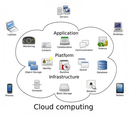
The “Cloud” in the term cloud computing, describes an image of the complex infrastructure, covering all the technical details. Obviously, the cloud computing has nothing to do with the weather “cloud”. It is just an analogy to give it a body to imagine. Cloud computing is a model for computing transforming. In this model, data and computation are operated somewhere in a “cloud”, which is some collection of data centers owned and maintained by a third party. This enables ubiquitous, convenient, on-demand network access to a shared pool of configurable computing resources that can be rapidly provisioned and released with minimal management effort or service provider interaction.
Cloud_computing
There are public cloud, private public and hybrid cloud. When a cloud is made available in a pay-as-you-go manner to the general public, we call it a public cloud. And when the cloud infrastructure is operated solely for a business or an organization, it is called private cloud. A composition of public and private cloud is called hybrid cloud. A hybrid cloud integrates the advantages of public cloud and private cloud, where private cloud is able to maintain high service availability by scaling up their system with externally provisioned resources from a public cloud when there are rapid workload fluctuations or hardware failures.
Optical Fiber Is the Key to Cloud Computing
In the “cloud” network, subscribers’ terminals are simplified into a pure and single device with only input and output functions but meanwhile utilize the powerful computing and processing functions from the “cloud”. This means that the terminal must have a very fast connection, because the simple terminal means fast network and powerful platform requirement, where “pipes” are put forward higher requirement. Thus, fiber is the ideal “pipe” for cloud computing. The following image shows the evolution of memory storage.
cloud-computing
In fact, computer applications, software and even file storage now reside on the Internet or in the “cloud”. Yet another driving force is mobile Internet traffic, which relies heavily on cloud computing. It is said that there is over 1 Exabyte of data currently stored in the cloud. And this number is growing exponentially every day. The greatest thing that will limit your ability to work seamlessly in the “cloud” is your Internet connection. Thus, to access the tremendous amounts data, we need fiber networks that can carry Terabits—one trillion bits per second. Fiber jumper cables can offer more available bandwidth and speed which meets the demands of the “cloud”. Obviously, no technology is more effective at meeting that challenge than fiber at present.
What’s more, FTTH infrastructure is expected as a solution to meet the growing demands for high bandwidth. It brings fiber optic connections directly into homes, allowing for delivery speeds up to a possible 100 Mbps, or even more. These speeds open the door to a variety of new services and applications for residential, business and public service markets. The relationship between FTTH and cloud computing is subtle. FTTH encourages the growth of cloud computing with its benefits. And cloud computing may in turn drives the development of FTTH.
Conclusion
As cloud computing market continues to mature, current and potential information technology capabilities offers many benefits to our lives. However, just like other new technology advancement, cloud computing also faces many challenges, which requires all of us to form thoughts on the strengths and downfalls of the technology. Fiber optic cable, as an indispensable component of network infrastructure, plays a vital role in cloud computing. After going through the whole passage, do you agree with me? Or what’s your opinion? You can leave your messages to share with us.

Thursday, April 7, 2016

How to Ensure Good Performance of Fiber Optic System?

We all know that transmission system is the key part of a fiber optic system. The performance of transmission system can directly affect the performance of fiber optic system. So what is the transmission system? The transmission system is a system that transmits a signal from one place to another. If you want to make sure the good performance of a fiber optic system, you should first ensure the transmission system in a good state. Next, today’s article will give you a list of basic items that may affect general transmission system performance. Only understand the following aspects can you know how to ensure the good performance of fiber optic system.
Fiber Loss Factor
Fiber loss generally has the greatest impact on overall system performance. The fiber strand manufacturer provides a loss factor in terms of dB per kilometer. A total fiber loss calculation is made based on the distance x the loss factor. Distance in this case the total length of the fiber cable, not just the map distance.
Type of Fiber
Most single-mode fibers have a loss factor of between 0.25 (1550nm) and 0.35 (1310nm) dB/km. Multimode fibers have a loss factor of about 2.5 (850nm) and 0.8 (1300nm) dB/km. The type of fiber used is very important. Multimode fibers are used with L.E.D. transmitters which generally don't have enough power to travel more than 1km. Single mode fibers are used with LASER transmitters that come in various power outputs for "long reach" or "short reach" criteria.
single-mode-vs-multimode
Transmitter
There are two basic type of transmitters used in a fiber optic systems. LASER which come in three varieties: high, medium, and low (long reach, medium reach and short reach). Overall system design will determine which type is used. L.E.D. transmitters are used with multimode fibers, however, there is a "high power" L.E.D. which can be used with Single mode fiber. Transmitters are rated in terms of light output at the connector, such as -5dB. A transmitter is typically referred to as an "emitter".
Receiver Sensitivity
The ability of a fiber optic receiver to see a light source. A receiving device needs a certain minimum amount of received light to function within specification. Receivers are rated in terms of required minimum level of received light such as -28dB. A receiver is also referred to as a "detector".
Number and Type of Splices
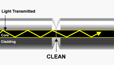
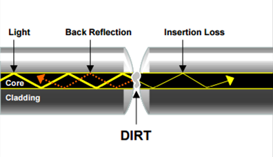
There are two types of splices. Mechanical, which use a set of connectors on the ends of the fibers, and fusion, which is a physical direct mating of the fiber ends. Mechanical splice loss is generally calculated in a range of 0.7 to 1.5 dB per connector. Fusion splices are calculated at between 0.1 and 0.5 dB per splice. Because of their limited loss factor, fusion splices are preferred. The following image vividly shows a good fiber connectivity and bad fiber connectivity, which may make a big difference in the insertion loss.
clean
dirt
Margin
This is an important factor. A system can't be designed based on simply reaching a receiver with the minimum amount of required light. The light power budget margin accounts for aging of the fiber, aging of the transmitter and receiver components, addition of devices along the cable path, incidental twisting and bending of the fiber cable, additional splices to repair cable breaks, etc. Most system designers will add a loss budget margin of 3 to 10 dB.
Selecting the Right Fiber Optic Cable
Of course, only knowing this is not enough. Fiber optic cable always plays an important part in the transmitting system. As a result, the quality of the fiber optic cable is of vital value to the whole fiber link. To choose a fiber optic cable, you need to know the following:
First: what type and grade of fiber is required? The system designer will have identified the fiber that is required for the network. Find the fiber type that is needed from the Fiber Specification and Selection Guide. Use the Fiber Type code to identify the fiber. This code becomes the first two digits of the catalog part number, replacing the XX notation. There are two common types of fiber optic cables—singlemode and multimode fiber optic cables.
fiber type
Then, how many fibers are required? The system designer will also have identified the number of fibers that will be in each cable. Fibers are usually cabled in groups of 6, 12, 24, 48, or 72.
Last but not least: what cable construction is needed? The cable construction that is needed is based on a variety of factors. We have a full range of products for premises, outside plant and indoor/outdoor to solve nearly every application need. Using the catalog as a guide, identify the cable type and construction that is needed. For example, Pull tab LC cable is a type of cable that uses MPO-HD to LC-HD Push Pull TAB connector.
Summary
To ensure the better performance of your fiber optic system, you are supposed to keep the above recommendations in your mind firmly. If you feel puzzled about how to ensure the better performance of your fiber optic system, you can also turn to a reliable vendor to help you out. Fiberstore as a rising telecom manufacturer, is committed to provide first-class services and high-quality products to our customers. For fiber optic cables, you can find many kinds with good quality and reasonable prices in FS.COM. A new type of fiber optic cable (Push-Pull patch cable) is also provided. Any questions, please feel free to contact us.