Showing posts with label single mode fiber patch cables. Show all posts

Thursday, August 18, 2016

Basic Information About Fiber Optic Cables

Nearly 40 years ago, fiber optic cable was made and installed, and it is still used today. Newer cables now being made are of even better quality. Compared to traditional copper wiring (commonly found in homes), fiber optic cables offer much higher data rates and are capable of reaching longer distances. This flexible and durable fiber is most commonly used to transmit light for a wide range of applications like visible light displays, sensors, and high-speed communications networks, which will be discuss in this article.
Fiber Optic Cables for High-Speed Applications
Although fiber optic cable is made of hair-thin glass or plastic to a desired length and diameter, inch for inch it’s stronger and steal and more durable than copper. For more detailed information about fiber vs copper, you can see a blog entitled “Why is the fiber optic technology better than copper?”. What’s more, there is no theoretical lifetime for optical fiber. And other key features of optical fiber are its electrical insulative properties, cost effectiveness, and improved security of the information being transmitted.
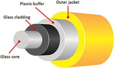
Fiber-optic-cable-structure
In terms of fiber optic cable construction, optical fibers have a transparent core which is surrounded by a transparent cladding material with a lower index of refraction, which helps to keep light in the core see in the above picture. Due to some leakage of light over a distance, attenuation is a result of the decrease in intensity of the light beam as it travels through the optical fiber. Attenuation is the most important limiting factor in the transmission of light signals (especially over long distances), although dispersion of the light is another factor that affects performance.
Single Mode and Multimode Fiber Optic Cables
Over the years, significant research and development has been invested into improving the general performance of fiber. Most are continuously improved upon to further minimize attenuation/loss and dispersion over longer distances and there are many subsets that apply to very specific network and performance standards. However, the two primary categories are single mode and multimode optical fibers.
Single mode fiber patch cables have a smaller diameter core (9µm) that only allows for one mode of light to propagate. As a result, the amount of light leakage decreases and minimizes the attenuation, allowing the signal to travel longer distances. Typically, single mode fiber is used for distances beyond several hundred meters by telecom and CATV service providers, government agencies, and major enterprises and universities with large campuses and networks.
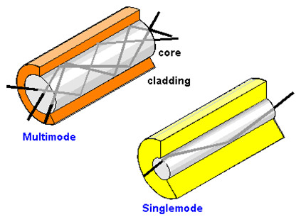
single mode and multimode fiber cables
Multimode optical fibers have a larger diameter core (50µm or 62.5µm) than single mode fibers, which allows for the propagation of multiple modes of light. The amount of light that passes through the core is increased, thus enabling a higher amoutn of information to pass through at any one time. Because of the higher rates of dispersion and attenuation, the signal quality is significantly reduced over longer distances, so multimode fibers are typically deployed for short distance applications within data centers, Local Area Networks (LAN) and other similar networks. Similar to single mode and other communication fibers, subsets of mutimode fiber types exist on the basis of construction/makeup (step-index, graded-index, etc) and for varying bandwidth rates over specific distances (OM2, OM3, OM4).
FS.COM Fiber Optics
Besides the single mode and multimode fiber optic cables, there are many standard and specialty for fiber optic cables existed for use within communications networks. For high-speed networking services, fiber optic network offers much higher internet speed and supports longer transmission distance, which makes it the clear choice for what’s now and what’s next.

Fiber optics FS.COM
FS.COM has been providing custom lengths of optical fiber to all of our customers for network simulation, latency, and system demonstration applications. All of our high-quality fiber cable assemblies such as Patch Cords, Pigtails, MCPs, Breakout Cables are ordered at lower price. Additionally, fiber optic cables are also divided by different connectors like LC to LC patch cord, ST-LC patch cord, SC to LC patch cable and so on. If you have any interest of our products, you can contact our experienced team for a free consultation.

Wednesday, June 8, 2016

Fiber Types and Corresponding Optical Transceivers

Fiber optic patch cable as the basic element of a network, transmits signals through strands of glass or plastic fiber. Fiber optic cables are available in multimode and single-mode fibers terminated with LC, SC, ST, LC, FC, MTRJ, E2000 connectors in simplex and duplex. The typical multimode fiber used in telecom or datacom applications has a core size of 50 or 62.5 microns. Single-mode fiber shrinks the core size down to 9 microns so that the light can only travel in one ray. Different fiber types like multimode or single-mode fibers connect with fiber optic transceivers resulting in different performances, which makes a huge impact on the network application. Here is what you need to know about the fiber types and the corresponding optical transceivers for network infrastructure.
Internal Structure of Single-mode and Multimode Fiber Optic Cable
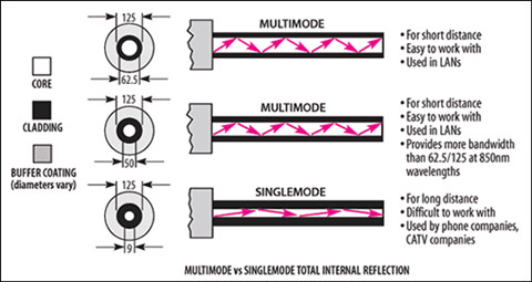
An optical fiber is a flexible filament of very clear glass capable of carrying information in the form of light. Single-mode fiber optic cable has a small diametral core of 9/125 microns that allows only one mode of light to propagate, which results in light reflections, lower attenuation and creating the ability for the signal to travel faster, further. That’s why single-mode fibers are typically used in long-reach applications.
internal structure of fiber optic cable
MM fiber patch cords, however, has a large diametral core of 50/125 and 62.5/125 in construction that allows multiple modes of light to propagate. Therefore, the number of light reflections created as the light passes through the core increases, creating the ability for more data to pass through at a given time. Because of the high dispersion and attenuation rate with this type of fiber, the quality of the signal is reduced over long distances. The above picture shows the inner structure of fiber optic cables.
Factors When Choosing Single-mode or Multimode Fiber
Different core diameters of single-mode and multimode fiber optic cables affect the optical properties and have a direct impact on system performance. Besides this, other factors like bandwidth, attenuation and costs also have the biggest impact on the system performance. Figure 2 gives you a vivid description of single-mode and multimode fiber.
single-mode and multimode fiber specification
Attenuation is the reduction of signal power, or loss, as light travels through an optical fiber. Fiber attenuation is measured in decibels per kilometer (dB/km). The higher the attenuation, the higher rate of signal loss of a given fiber length. Single-mode fibers generally operate at 1310 nm (for short range) while multimode fibers operate at 850 nm or 1300 nm. Attenuation is not usually considered to be the main limiting factor in short rang transmissions. But it can cause big differences in high speed network such as 100Gb/s.
Bandwidth means the carrying capacity of fiber. For single-mode fiber, the modal dispersion can be ignored since its small core diameter. Bandwidth behavior of multimode fibers is caused by multi-modal dispersion during the light traveling along different paths in the core of the fiber. It has an influence on the system performance and data rate handling. Multimode fiber uses a graded index profile to minimize modal dispersion. This design maximizes bandwidth while maintaining larger core diameters for simplified assembly, connectivity and low cost. So manufacturers start to develop higher-performance multimode fiber systems with higher bandwidth.
Costs: A fiber optic transceiver usually consists the optical light sources, typically LED–light emitting diode and optical receivers. Since the core diameter size and primary operating wavelengths of single-mode fiber and multimode fiber are different, the associated transceiver technology and connectivity will also be different. So is the system cost.
To utilize the single-mode fibers generally for long distance applications, transceivers with lasers that operate at longer wavelengths with smaller spot-size and narrower spectral width. But these kinds of transceivers need higher precision alignment and tighter connector tolerance to smaller core diameters. Thus, it causes higher costs for single-mode fiber interconnections. To lower the cost, manufacturers produce transceivers based on VCSEL (vertical cavity surface emitting laser), for example, 10G-SFPP-SR is a SFP+ transceiver support a link length of 300m, which are optimized for use with multimode fibers. Transceivers applying low cost VCSEL technology to develop for 50/125μm multimode fibers, take advantage of the larger core diameter to gain high coupling efficiency and wider geometrical tolerances. OM3 and OM4 multimode fibers offer high bandwidth to support data rates from 10Mb/s to 100Gb/s.
Fiber Type and Associated Optical Transceiver Compatibility Matrix
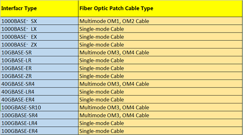
From a technician's standpoint, optical transceivers should be compatible with fiber optic cables, meaning that multimode transceivers should only connect with multimode fiber optic cables, or you may end up with an error. Table 3 summarizes various optical interfaces and their performance over the different fiber types. The table specifies the maximum reach achievable over each fiber type and the requirement for a mode conditioning patch cord.
single-mode-multimode-fiber-optic-patch-cable
This table is directly derived from the IEEE 802.3-2005 standard, if you comply with the standard, these performances are guaranteed and longer reaches may be achievable depending on the quality of each link. To ensure whether a link can work, all you can do is to try and see if the performance is satisfactory. The link should be either error-free for critical applications, or the bit error should remain below 10-12 as per minimum standard requirement. For instance, it may be possible to reach much longer distances than 550 m with an OM3 laser-optimized fiber and 1000BASE-SX interfaces. Also, it may be possible to reach 2 km between two 1000BASE-LX devices over any fiber type with mode conditioning path cords properly installed at both ends. Single mode fiber patch cables as noted before, are suitable for long-haul application. Although the optics are more expensive, they’re offering much longer reach, which makes them an ideal choice for network infrastructure.
Conclusion
Choosing the right fiber for your network application is a critical decision. Whether to use single-mode or multimode fiber for your infrastructure, no one can give your the best answer. Only by fully understand the system requirements and select the appropriate fiber can you maximize the value and performance of your cabling system. FS.COM offers cost-effective fiber optic patch cables to meet the requirements of all the customers. If you are interested, please send your request to us.

Monday, May 30, 2016

It’s Time to Deploy FTTH

Fiber to the home (FTTH) developments clearly influence the demand for today’s home purchases. Developers and home builders recognize the need for reliable high-speed broadband communications. Thus they should seize the opportunity to design FTTH network during the design and construction of the development. In fact, deploying FTTH in a new development is at cost similar with deploying copper at the same location. But the long-term benefits stemming from fiber-ready infrastructure further catch people’s attention. Unlike coax and xDSL, fiber is more than just fast. So why implement FTTH development? The following article will give a further illustration of the reasons.
Fast Bandwidth
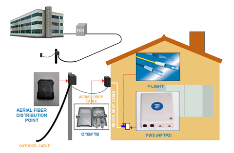
Cable modem and xDSL helped residential broadband get off the ground. Now, however, the sheer speed of fiber overcomes bandwidth limitations of coax and copper. To illustrate, rising consumer demand for big-screen LCD displays can chew up 19 Mbps of bandwidth per channel. In addition, broadband connections are constantly clamoring for more band-width, both upstream and downstream. With busier lives, families want high-speed broad-band communications to transfer e-mail, digital photos and Internet files and they also want entertainment options such as time-sensitive, interactive video gaming that requires bi-directional bandwidth capability. With the typical household having three or more TVs and the ferocious appetite of broadband vying for capacity, it is easy to see that an abundant supply of fiber bandwidth must be included in the design and construction of the development. Figure 1 shows the basic FTTH architecture.
BASIC-FTTH-ARCHITECTURE-LANDED-PROPERTIES-SOLUTION
Reliable Capacity
Noisy channel conditions, inclement weather, environmental clutter such as buildings and trees, corroded connections and distance limitations can all impact the reliable delivery of residential broadband. However, the FTTH network access architecture is immune to all of these conditions so there is virtually no downtime. In addition, economical battery backup at the residential NID automatically kicks in when line power is interrupted. Furthermore, FTTH assures the demanding subscriber that they always receive the high-speed broadband capacity that they are paying for, both upstream and downstream, no matter how loaded the access network may be. This built-in reliability is no longer the exception but rather what the homeowner now expects and the builder’s life becomes much easier with satisfied homeowners.
Easy Deployment
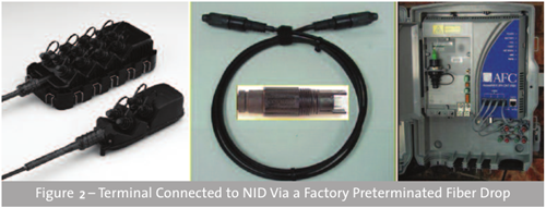
Making the optical channel ready for signals once required a skilled technician to carefully splice fiber cables together. Today, the success of FTTH is no longer tied to fiber splicing in the field. As already alluded to, the distribution and drop segments of the FTTH network are easily deployed and intuitively connected. For example, the preterminated fiber drop can reduce subscriber connection time by up to 50 percent because it can be easily screwed into the terminal and the NID by an installer who does not need to know anything about fiber. In the distribution segment, the ease of deployment can shave off 80 percent of the deployment time, because once the terminal distribution system has been placed, homes are immediately ready to be connected into the network.
terminal process
In addition, with FTTH, there is no need for high-voltage power supplies in the neighborhood. Manufacturers are also continuing to improve the appearance and reduce the size of fiber cabinets and terminals relative to the traditional copper products. Combined, this results in a much more aesthetically pleasing deployment than ever before.
Future Proofing
An FTTH network offers land developers an enviable return on their investment capital. Timely planning today can net thousands of dollars in profit. For example, if you invest $500 per home to deploy the fiber jumper and connecting hardware and the home then sells for $5,000 more than it would have otherwise, your investment just returned a handsome 1000 percent profit. That is easy math and easy money.
The return on fiber investment does not stop with its deployment, however. The network operator will also appreciate that robust, reliable and cost-effective FTTH network as they seriously consider their operational expenses. For example, an optical access network featuring segments that can, by design, be quickly connected together not only reduces the upfront deployment cost but also will reduce the amount of time required to turn up subscribers, test and troubleshoot the network. As the triple-play battle for the residential customer continues, a preterminated FTTH network can make the business case very enticing because it sets the network operator’s stage for reduced operational costs and additional revenue from advanced services such as home security and home networking.
Operationally, fiber drop cables are quickly and easily screwed into terminals and residential network interface devices (NID) across the country to save both time and money. Without these key advances in FTTH technology that reduce capital and operational costs, FTTH would continue to wrestle its competitors but now FTTH wins the access investment hands down.
Beneficial Solution
Modern day residential services like HDTV and high-speed broadband that enhance the quality of life in homes are being delivered via FTTH. Looking forward, FTTH residential developments ensure that advanced services such as telecommuting, telemedicine and distance learning will all be transparently realized. FTTH results in reduced commutes and environmental pollution, prolonged quality of life, and education, education, education. Broadband communications is a key element in an increasingly competitive global economy. With FTTH, the world will be better positioned for social and economic prosperity.
Summary
To sum up, FTTH deployment is unstoppable with all the positive impacts that fiber affords. If you are still waiting for service providers to install cable and manually turn up services, then you are left behind. Fiberstore provides a full range of fiber jumper cables suitable for FTTH deployment. MM fiber patch cords and single mode fiber patch cables are also available. Come to us if you have any request for our products.