Showing posts with label fiber optic connector. Show all posts

Thursday, December 29, 2016

Why Should We Keep Fiber Optic Connectors Clean?

Fiber optic technicians are aware that dirty connections can cause attenuation, but they may not realize that it can also cause bit errors or slowdown of the network. Therefore, keeping the fiber optic connector endfaces clean is one of the most overlooked aspects of fiber optic maintenance and troubleshooting. Today’s article will describe the detailed information about how dirty fiber optic connector can cause slowdown of the network.
Brief Overview of Fiber Optic Connectors
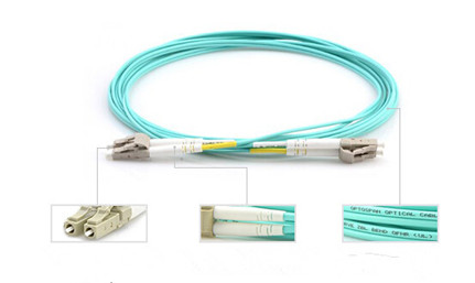
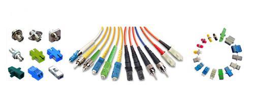
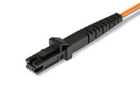
A fiber optic connector is urgently needed to the industry owing to the lower loss, lower cost, easier to terminate or solved some other perceived problem. As a result, about 100 fiber optic connectors have been introduced to the marketplace, but only a few represent the majority of the market. Commonly used fiber optic connector types like the SC, FC, LC, ST, MU, E2000, MTRJ, SMA , DIN as well as MTP & MPO etc, which are widely used in the termination of fiber optic cables, such as fiber optic pigtail, fiber optic patch cables and so on.
How Does the Dirty Fiber Optic Connector Cause Bit Errors?
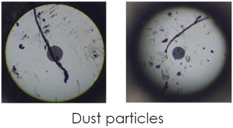
Of course, the dirty fiber connection will cause bit errors as the contamination degrades the signal quality. In fact, the signal comes in a beam of light traveling through the fiber’s core. When the light travels through the fiber core, it has a refractive index value. But when the light beam comes into contact with end face contamination, it will enter a second medium which has different refractive index value. That’s the reason why it causes the bit error rates.
fiber-conn-dust
Figure 1: dust particles under the microscope
Sometimes, in fiber optic network, we need to mate two fiber optic connectors together. Will the mating prevent fiber optic connector from contamination? The answer is yes. There is no need to worry about dust with physical contact connectors as long as they were cleaned before the mating process. When the two ferrules are physically mated, the mating force for most single fiber industry standard connectors is around 1kg or about 2.2lbs. If you calculate the force of what 2.2lbs in a 200μm, that comes to 45,000psi which is why contaminate migration is not a problem even in a dusty environment. The following part will provide some answers to some common questions of end users.
Will the Dust Cap Make Fiber Endface Clean?
No, customers should never assume that a capped cable assemblies is clean when taking out of the bag. Dust and mold release agents are the two common contaminates but nearly invisible for the human eyes. The primary purpose of the end cap is to protect the ferrule end face from scratch and pitting defects. It does not protect the ferrule end face from contamination.
If a customer buys a new fiber jumper from the manufacturer and inspects it after taking the end caps off, it would not be uncommon to see some small amount of on contamination on the endface. This does not mean that the jumper manufacturer’s quality process are lacking. All manufacturers experience this. The customer just needs to work smartly and realize that the end cap is just for protecting against scratches. The best practice is to inspect the ferrule, clean if necessary and re-inspect before mating. If the customer does not have a ferrule scope available, then cleaning both connectors end faces before mating will significantly reduce the likelihood of damage and cross contamination.
How to Keep the Fiber Optic Connectors Clean?
Keeping fiber connections clean is different from any other type of cleaning due to the relative sizes of the connectors compared to the particles and contaminants that typically reside on them. Also we need to be diligent in their maintenance by cleaning the connectors every time before they are mated and after each un-mating. Static charges attract dust to the fiber connectors and prevent them from falling off even when blown with a can of compressed air. As we have discussed in the above article, dust caps are primarily used to protect the ferrule and can actually make a clean connector dirty due to their tendency to keep a static charge.
one-click-cleaner
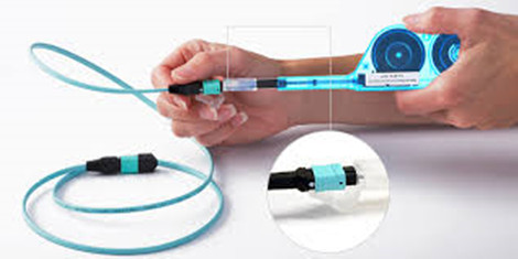
Figure 2: use one-click cleaner to clean the MPO cable
The mechanical cleaning tools like the One-Click cleaners are widely used in the optical fields. . One-click cleaner is designed to clean male connectors, female bulkhead adapters, fiber patch cables and test equipment. It cleans the ferrule endface removing from dust, oil and other contamination without scratching the endface. Although it is the most cost-effective and time-saving solution for cleaning fiber optic connectors, it has a limited contact region and will never be able to clean the connector’s end face. Therefore, another fiber optic cleaner has given to birth—Fiber Optic Cassette Cleaner. The cassette cleaner can wipe away contamination from optical connector endface with ease. I’s very easy to use and suitable for LC/MU/SC/FC/ST/MPO/MTRJ connectors. Usually, the body of this cleaner is made from antistatic materials which will not produce dust.
Is Dry Cleaning a Better Solution?
Besides the mechanical cleaning tools, there are two basic methods :dry cleaning and wet cleaning. There are two distinct advantages a wet cleaning process has over the dry process. The first process is static dissipation and the second is the cleaning solvent’s ability to loosen up harden contaminates from the ferrule end face without causing permanent defects to the end face.
On the other hand, the dry wiping process that an operator would do using a Fiber Optic Cassette Cleaner or One-Click cleaner relies on contact friction to remove contamination. When two materials are rubbed together, there is a transfer of electrons between the two surfaces and the imbalance on the surface creates a charged electric force we call static electricity. The two surfaces, one charged positive and the other negative, will try to pull in surrounding particles to being the charge back into a neutral balance. This attraction pulls in the dust particulates in the air and the wear debris on the connector body and adapter. The introduction of a cleaning solvent during a wet-dry cleaning process introduces static dissipative medium for the charge so that it does not stay on the ferrule surface.
Conclusion
End users should be wise to think of the environment his connectors are being exposed before learn to keep fiber optic connector clean. Because a large enough piece of dust particulate residing somewhere on either ends will create problems. The best practice to avoid long-term problems and extend the life of your optical assemblies is to always inspect and remove any contamination regardless of the connector type. FS.COM offers a full range of fiber optics that can cater to your specific requirement. Bulk Ethernet cable, fiber jumpers, transceivers  and DAC/AOC cables are in great selection. Please feel free to contact us.

Tuesday, July 12, 2016

A Quick Lesson in Fiber Optics

Fiber optics, with its high bandwidth capacities and low attenuation characteristics, is considered to be the ideal building equipment in the telecommunication field. Depending on the type of application and the reach to be achieved, various types of optical fiber may be considered and deployed. This article is devoted to provide solutions to the questions about fiber optic cables. After going through the whole passage, you might form a basic understanding of optical cables.
What Is an Optical Fiber?
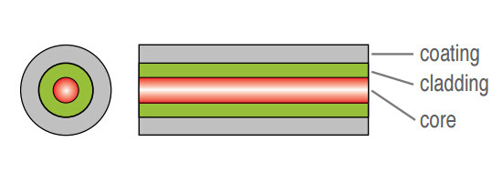
Core and cladding are the two main elements of an optical fiber. The core as shown in the image below, is the axial part of the optical fiber made of silica glass, which is the light transmission area of the fiber. The cladding is the layer completely surrounding the core. The refractive index of the core is higher than that of the cladding, so that light in the core strikes the interface with the cladding at a bouncing angle, gets trapped in the core by total internal reflection, and keeps traveling in the proper direction down the length of the fiber to its destination.
internal structure of fiber optics
There is usually another layer, called a coating surrounding the cladding that typically consists of protective polymer layers applied during the fiber drawing process, before the fiber contacts any surface. As we all known, the most typical types of fiber optic cable are MM fiber patch cords and single mode fiber optic cables.
How Do Fiber Optics Work?
Fiber optics use light pulses to transmit signals from one end to another. Light passes through the optical cable, bouncing off the cladding until it reaches the other end of the fiber channel, which is called total internal reflection. The diameter of the core corresponds directly with the angle of reflection.
As this diameter increases, the light requires more reflections and a greater amount of time to travel a given distance. For example, single mode fiber optic cable has a smaller diameter core which makes itself suitable for long distance, higher bandwidth runs. Multimode fiber, however, has a larger diameter core and is more commonly used in shorter cable runs.
What You Need to Know About Optical Fiber?
Attenuation and Wavelength
Light is gradually attenuated when it is propagated along the fiber. The attenuation value is expressed in dB/km. It is a function of the wavelength (λ), meaning that the operating wavelength to transmit a signal in an optical fiber is not any wavelength. It corresponds to a minimum of attenuation.
The typical operating wavelengths that light sources have been developed for are 850 nm and 1300 nm in multimode, and 1310 nm and 1550 nm in single mode. For a 850 nm operating wavelength, there is a 3dB light attenuation after 1 km propagation. 3 dB means that half of the light has been lost.
Bandwidth
Bandwidth is a measure of the data-carrying capacity of an optical fiber. For example, a fiber with a bandwidth of 500 MHz.km (Mega-hertz kilometer) can transmit data at a rate of 500 MHz along one kilometer. Bandwidth in single mode fibers is much higher than in multimode fibers.
How to Link Two Optical Fibers?
Fusion Splice
This operation usually needs a fusion splicer to accomplish the process. In this method, optical technician directly links two fibers together by welding with an electric arc, by aligning best possible both fiber cores. Compared with other method, this linking method is fast and relatively simple to make. And the light loss generated by the welding, due to an imperfect alignment of the cores, remains very weak.
However, just as the coin has two sides, this link method has drawbacks. In spite of a protection of fusion by a heat-shrinkable tube, this type of link is relatively fragile. It is a permanent link. What’s worst, the fusion splicer is usually very expensive.
Use of Connectors
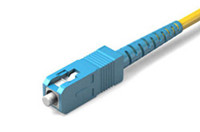
In this case, it is necessary to terminate a connector at each end of the fibers to be connected. The two fibers can then be connected by connecting the two connectors together. The following picture shows a SC fiber patch cord.
SC fiber patch cord
Just as the following picture shows, this type of connection is robust. The type of connector can be chosen according to the application field of the system. Unlike fusion splice, this connection is removable. It is possible to connect and disconnect two fibers hundreds to thousands times without damaging the connectors. But the implementation is longer than fusion, and requires an experiment as well as specific tools. Furthermore, the light loss due to connection is higher than in the splicing solution.
Why to Choose Fiber Optics?
The main advantages of fiber optics are the followings:
  • Lower loss: Optical fiber has lower attenuation than copper conductors, allowing longer cable runs and fewer repeaters.
  • Increased bandwidth: The high signal bandwidth of optical fiber provides a significantly greater information-carrying capacity. Typical bandwidths for multimode fibers are between 200 and 600 MHz.km, and > 10 GHz.km for singlemode fibers. Typical values for electrical conductors are 10 to 25 MHz.km.
  • Immunity to interference: Optical fibers are immune to electromagnetic and radio frequency interference and also emit no radiation themselves.
  • No detection: Standard fiber optic cables are dielectric, so they cannot be detected by any type of detector.
  • Electrical isolation: Fiber optics allows to transmit information between two points at two different electrical potentials, and also next to high voltage equipments.
  • Decreased size and weight: Compared to copper conductors of equivalent signal-carrying capacity, fiber optic cables are easier to install, require less duct space, and weight about 10 to 15 times less.
Conclusion
The Internet nowadays is largely based around optical fiber. For those who do not understand fiber optics, they will have confusion and misconceptions when working with fiber optic networks. This article probably will not make you an optical engineer, but it will guide you to touch on a little bit of every topics, from the theoretical to the practical even if you aren’t designing optical networks. FS.COM offers s variety of fiber optic cables with the highest quality and low price. If you are interested, you can contact us.

Thursday, June 30, 2016

Guide to Fiber Optical Connectors

Fiber optical cable is the composite material, typically consists of a hair-thin glass used to transmit pulses of light instead of electrical signals. Thus the termination must be much more precise. Compared with copper cables end with RJ connectors, fiber optic connectors must align microscopic glass fibers perfectly to make metal to metal contact. There are many different types of fiber connectors, they share similar design characteristics, such as LC to LC patch cord, single mode LC to ST fiber patch cable, single mode fiber ST to SC patch cord, single mode fiber cable with LC connector, etc. Nowadays most cables are ended with the same connector, which poses a problem for users to sort through cables and connectivity options. That’s why this article is provided here to help out the illustration of fiber optics and optical connectors.
fiber-optic-connector
Internal Structure of Optical Connector
Fiber optic connector terminates the end of fiber optic cable, enabling quicker connection and disconnection than splicing. As noted before, optical connector has to be aligned properly to the microscopic glass fibers completely in order to allocate for communication. There are three major components of a fiber connector: the ferrule, the connector body, and the coupling mechanism.
  • Ferrule
It is a thin structure that is actually used to holds the glass fiber, which has a hollowed-out center that forms a tight grip on the fiber. Ferrules are usually made from ceramic, metal, or high-quality plastic, and typically will hold one strand of fiber.
  • Connector Body
This is a plastic or metal structure that holds the ferrule and attaches to the jacket and strengthens members of the fiber cable itself.
  • Coupling Mechanism
This is a part of the connector body that holds the connector in place when it gets attached to another device. It may be a latch clip, a bayonet-style nut, or similar device.
Different Types of Fiber Optic Connectors
To sum up, there are nearly 100 fiber optic connectors on the market, but only a few are available that was lower loss, lower cost, easier to terminate. Optical connectors like LC connector, SC connector, ST connector, FC connector, RJ45 connector, MT-RJ connector are the representative that will be present to you.
  • SC Connector
SC
SC or square connector, was developed by Nippon Telegraph and Telephone on the market, slowly grew in popularity as manufacturing cost went down. Now it is becoming increasingly popular in single-mode fiber optic cable, analog CATV, GPON, GBIC. SC is a snap (push-pull coupling) connector with a 2.5mm ferrule diameter that operates on the standard IEC 61754-4. The connector’s outer square profile together with its snap coupling mechanism that allows greater connector packaging density in instruments and patch panels. The SC fiber patch cord is ideally suited for datacoms and telecoms applications including point to point and passive optical networking.

  • LC  Connector
LC
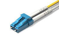
LC or Lucent Connector, is a push-pull, small form factor connector that uses a 1.25mm ferrule, half the size of the SC. Due to the combination of small size and latch feature, LC connector is ideal for high-density connections and usually utilized in SFP, SFP+, XFP, and single-mode QSFP+ transceivers. Along with the development of LC compatible transceivers and active networking components, it will continue to grow in the FTTH arena.


  • FC Connector
FC
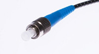
FC or Ferrule Connector., is a round, threaded fiber optic connector that was designed by Nippon Telephone and Telegraph in Japan. The FC connector is applied for single-mode fiber and polarization-maintaining optic fiber. The FC is a screw type connector with a 2.5mm ferrule, which was the first fiber optic connector to use a ceramic ferrule. However, FC is becoming less common and gradually replaced by SC and LC connectors because of its vibration loosening and insertion loss.

  • ST Connector
ST
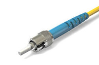
ST or Straight Tip, was developed by AT&T shortly after the arrival of the FC. They may be mistaken for one another, but ST uses a bayonet mount other than a screw thread. And you have to make sure SC connectors are seated properly owing to its spring-loaded structure. SC is mainly used in multimode fiber optic cable, campuses and buildings.


  • RJ-45 Connector
RJ45
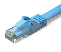
RJ-45 connectors are physically wider than the RJ-11/12 connectors used for telephone. In network applications, RJ-45 cable assemblies are used to connect from a patch panel to a network switch, and also to connect a computer's NIC to a data port.


  • MT-RJ Connector
MJRJ
The MTRJ connector closely resembles an RJ-style modular plug, even getting part of its name from the resemblance. It is covered in the TIA connector intermateability standard FOCIS-12 (TIA-604-12). MT-RJ is a duplex connector with both fibers in a single polymer ferrule. It uses pins for alignment and has male and female versions. Multimode only, field terminated only by prepolished/splice method.


Conclusion
Whether you are about to install a new fiber optic network, or perhaps you are maintaining on an existing one, you are supposed to have a basic knowledge about fiber optics and optical connector. This article simply illustrates the most commonly used fiber optic connectors on the market to help you sort through the optical connectors. But if you’re still not sure which fiber optic connectors are right for you, or perhaps you’d like some more information you can always get in touch with FS.COM.