
Optical fiber is the ideal transmission medium for light signals in contrast to copper cable, and it rarely needs amplification. When the signals carried by light travel through the core of fiber jumper cables, the strength of the light will be weaker, as it’s impossible not to incur degradation of light over the length of the network connection. It is inevitable, but if the signal becomes too weak, it will affect the performance of the fiber optic network. So understanding and tackling these losses is a critical part of network installation and testing.
This loss of light power is generally called fiber optic loss or attenuation (measured in dB). High-quality single-mode fiber will often exhibit attenuation. The cause of fiber optic loss located on two aspects: internal reasons and external causes of fiber optic, which we often use the term insertion loss (IL) and return loss (RL) to describe it.
Insertion Loss
Insertion loss refers to the measurement of light that is lost between two fixed points in the fiber, which usually occurs when optical fibers are spliced together, connected, or sent through additional passive network components. It is often attributed to misalignment, contamination, or poorly manufactured connectors (ferrules) and has long been used to advocate fusion splicing. However, in reality, the attenuation difference between fusion splicing and manual connections is marginal (less than 0.1 dB).
Optical connectors might be most likely the cause of high IL, but it’s unfair to think of them as the only culprit. I have watched a splice engineer perform a perfect fusion splice onto a mass-produced, low-cost commodity pigtail, because the Optical Network Terminal (ONT) called for an SC or LC connector. In reality, we can manage connector losses by stipulating the IL standards of the cables we buy, and training installers to keep things clean. Reducing the number of components within the network also logically lowers the insertion loss.
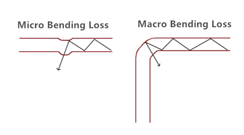
Furthermore, micro and macro-bending (see in Figure 2) may attribute to significant IL, or cracks to the glass caused by over-tensioning (pulling) or by crush and impact damage. This is often the worst kind of attenuation because it takes time to develop and is much more difficult to pinpoint.
Another reason for fiber seemingly exhibiting high IL in fiber to the home (FTTH) networks is the route of the cable itself. For example, a fiber might travel 10km from the OLT to the curb and lose less than 1dB, and then go on to lose three times as much in the next 100 meters. Multi dwelling units (MDUs) are a great example of complex fiber routes, and it is especially important to protect bend radii, such as with dedicated raceways or microducts. Fiber can quite easily become tightly coiled or kinked during installation; even bend insensitive G657A1 fiber coiled just once to 20mm diameter will see as much as 0.2dB loss. Coiled twice at 20mm 0.4dB, three times and... you get the picture.
Return Loss
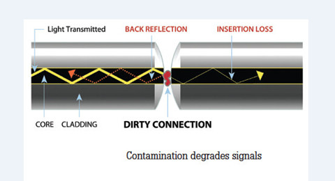
Fiber Return loss also have great impacts on the network’s performance (see in Figure 3). It refers to the amount of signal reflected back towards the source due to an impedance mismatch effectively, if this is too high, the laser within the network may stop transmitting correctly. Many systems can cope with 40dB return loss (RL), equivalent to 0.01 per cent of the power being sent back. FTTH, however, is more demanding, and RL cannot be more (lower) than -60dB, sometimes higher.
Cable, specifically, can show high RL if a gap exists (such as fiber undercut) or if the fiber is broken. Contamination, torsion, strain or poorly seated connectors can also lead to high return losses. Therefore, it is important that networks are tested to ensure that there aren’t any unexpectedly high RL figures that indicate problems with equipment or fibers. To achieve these ultra-low RL figures, optical connectors must have angled ferrules (APC).
Insertion loss and return loss are not the same thing and, therefore, need to be measured separately. Measuring the RL on the fiber will pinpoint the issue as the response would be unexpectedly high. The complexity of fiber networks, and the need to measure optical losses, can potentially lead to confusion. However, careful planning, use of high-quality components and a focus on testing will enable installers to deliver high-speed connections that perform well over the long term. Here are five easy tips for reducing your losses.
Tips for Reducing Fiber Loss
1. Minimize tight bends that cause light to refract through the fiber cladding. If you need to coil fiber, keep the radius as large as possible.
2. Clean connector ferrules little and often - especially before and after testing—and always use the right tools and consumables.
3. Decide which is higher: your "power loss" budget or your cable inventory budget. Buying cheap fiber can create larger costs further down the line.
4. Avoid any undue stress on the fiber, particularly during installation. Push where possible and if a cable needs pulling, do not exceed the cable’s maximum tensile load.
5. Minimize the number of splices or connections in your network; if it means better planning or more innovative drop cables, the investment is probably well worth it.
Conclusion
The power or strength of the signal is typically higher at the head end of the optical network, but lower at the other end because of the fiber loss. To ensure smooth fiber optic transmission, fiber optic loss must be decreased. You can follow the above tips to help you out. FS.COM provides a variety of fiber optic patch cables that are well tested for insertion loss for high quality before shipment. For example, LC to SC patch cord is offered. If you have any requirement of our products, please send your request to us.
Thank you for the information Fiber optic network cabling
ReplyDelete