Showing posts with label OM3. Show all posts

Wednesday, April 26, 2017

How to Choose Fiber Optic Cable for 10G SFP+ Optical Transceiver?

How to choose fiber optic cables for 10G SFP+ transceivers? It seems like a dumb question for most of the fiber optic technicians. However, there are still some people, especially the green-hand network installers, may not know the compatibility between fiber optic cables and optical transceiver modules. Today, I want to make a clear illustration of how to choose the right transmission media (OS2/OM3/OM4/Cat6/Cat6a) for 10G SFP+ optical transceiver modules.
Overview of SFP+ Optical Transceiver Module
Before coming to the main part of this article, let’s first have a brief overview of the SFP+ optical transceiver modules and 10G fiber & copper cables.
  • 10GBASE SFP+ optical transceivers
SFP+ optical transceivers, according to the IEEE standards, can be divided into several types, for example, 10GBASE-LRM SFP+, 10GBASE-LR, 10GBASE-ER SFP+, 10GBASE-ZR SFP+, 10GBASE-SR SFP+, 10GBASE-T SFP+. Each SFP+ optical transceiver type has its own specification and usage that are not be listed here. For more, please review the previous articles.
  • BiDi SFP+ Modules
Besides the above 10GBASE SFP+ modules, 10GBASE-CWDM SFP+, 10GBASE-DWDM SFP+ and SFP+ BiDi optical transceiver modules are also the most commonly used 10G SFP+ optics. SFP+ BiDi optical transceiver usually uses two different wavelength to achieve 10G transmission over one fiber. The most frequently used wavelength of BiDi optical module is 1310nm/1550nm, 1310nm/1490nm, 1510nm/1590nm.
bidi-10G-SFP+--transceiver-simplex-cable
  • CWDM/DWDM SFP+ Modules
The Coarse Wavelength-Division Multiplexing (CWDM) and Dense Wavelength-Division Multiplexing (DWDM) SFP+ optics are the convenient and cost-effective solution for the adoption of 10 Gigabit Ethernet in campus, data-center, and metropolitan-area access networks. This 10G fiber optic transceiver type can support up to eight channels of 10GbE over single-mode fibers for distance over 80km.
10G Fiber & Copper Patch Cables
Fiber optic cables can be categorized into two types: single-mode and multimode fiber optic cables. They have different core size and fiber optic transmission equipment, which makes them suitable in different applications. Single-mode fiber patch cables, or OS1/OS2 (OS1 is now not popular on the market) are normally used for long-distance transmission with laser diode based equipment.
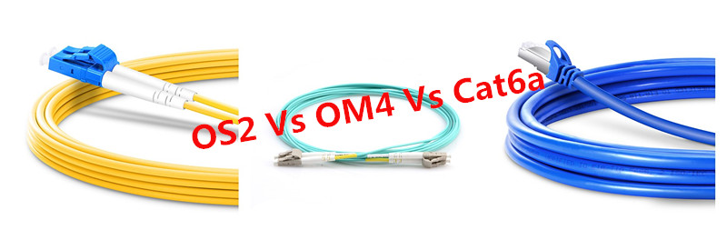
OS2 OM4 Cat6a for 10G SFP+ module
Multimode fiber cables, or OM1/OM2/OM3/OM4, have a relatively large light carrying core, usually utilized for short-distance transmission with LED based equipment. OM1, with a core size of 62.5um, supports 1GB network within 300m. OM2 (50um) can support up to 10GB, with a distance of 600m. OM3 and OM4 are the laser-optimized multimode fibers, which can be used in 10GB network with a link length of 300m, 550m respectively. These types of optical cables can be also used on 40G/100G network utilizing a MTP/MPO connector.
Cat6/Cat6a cables are the Copper Ethernet Network cables used for 10G network. Compared with Cat5e (1 Gigabits of data) and Cat5 cables (10/100 Mbps), Cat6 is the Ethernet cable that can handle up to 10Gbps with the distance limited to 164ft. Cat6a is the advanced version of Cat6 cables that further reduce crosstalk, which makes it can support the full 328 feet of Ethernet cable.
Choosing Fiber Optic Cables for 10G SFP+ Optical Transceivers
As noted before, single-mode patch cables can be used for 10G 10GBASE-LRM SFP+, 10GBASE-LR SFP+, 10GBASE-ER SFP+, 10GBASE-ZR SFP+, 10GBASE-CWDM SFP+, 10GBASE-DWDM SFP+ and SFP+ BiDi modules.
Cable TypeConnectorMax Distance
10GBASE-LRM SFP+9/125 SMFLC Duplex200m
10GBASE-LR SFP+9/125 SMFLC Duplex10km
10GBASE-ER SFP+9/125 SMFLC Duplex40km
10GBASE-ZR SFP+9/125 SMFLC Duplex80km
CWDM SFP+9/125 SMFLC Duplex80km
DWDM SFP+9/125 SMFLC Duplex80km
SFP+ BiDi9/125 SMFLC/SC Simplex80km

Multimode fibers, especially the OM3 and OM4 cables, are supported for 10GBASE-SR SFP+ transceiver modules. The following chart displays the part No. of customized OM3 and OM4 cables.
Customized Part IDConnectorFiber ModePolish TypesJacketStock Length
17235LC Duplex50/125 OM4UPCPVC1m-30m (3ft-98ft)
17235LC Duplex50/125 OM4UPCLSZH1m-15m (3ft-49ft)
17235LC Duplex50/125 OM4UPCOFNP1m-15m (3ft-49ft)
12018LC Duplex50/125 OM3UPCPVC1m-30m (3ft-98ft)
12018LC Duplex50/125 OM3UPCLZSH1m-30m (3ft-98ft)
12018LC Duplex50/125 OM3UPCOFNP1m-15m (3ft-49ft)

Cat6 and Cat6a Patch cables can be only used on the 10GBASE-T SFP+ transceivers.
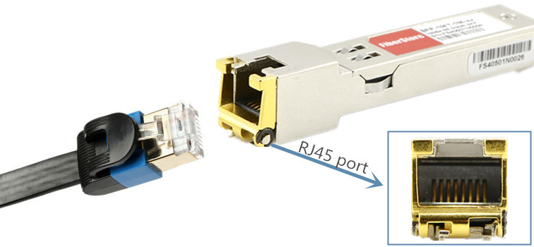
10GBASE-T RJ45 SFP+ Copper module
Keep in mind, the newly available SFP+ copper transceiver modules can only support up to 30m.
Conclusion
This article lists all the existing the 10G fiber & copper patch cables and SFP+ transceiver module types, as well as the guidance about how to select the right patch cables for 10G SFP+ optical transceivers. FS.COM offers a full range of SFP+ optical transceiver modules and patch cables. Please contact us if you need any help.

Monday, March 28, 2016

Some Basics About Migration to 40G Ethernet

Fiber optic links are vital for providing the bandwidth and speed needed to transmit huge amounts of data to and from a large number of sources. Recently more bandwidth is greatly needed to support the use of virtualization and improved space utilization in the data center. 2010 witnessed the ratification of 40 and 100 gigabit Ethernet (GbE) standard, since then leading switch manufacturers offered 40 GbE blades and more than 25% of data centers have implemented these next generation speeds. It is anticipated that by the end of this year, more and more data centers will follow suit. Therefore today’s article will provide an effective solution to help you migrate from current data center applications to 40/100 GbE.

10G OM3/OM4 Connectivity in the Data Center
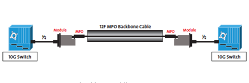
The IEEE 802.3ae 10G standard released in 2002 included 10GBASE-SR OM3 guidance that can operate at 850nm with duplex fiber serial transmission. Even though duplex fiber implied duplex LC connectivity throughout the channel, 12F MPO terminated cables emerged as a primary choice for deployment in data-center backbone applications. The 12F MPO terminated trunk cable provided the highest fiber packing density to maximize pathway and space utilization in ducts, raceways, and patch panels. For example, 46C3447 is IBM BNT 10GBASE-SR SFP+ that operates over OM3 cable for a distance of 300m with LC duplex connector. An MPO connectorized backbone cable typically is terminated in patch panels using one of two methods that break-out the 12F MPO to six 2F duplex LC (Figure 1).

10G connectivity
Standards From 10GbE to 40/100GbE
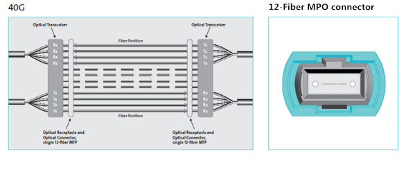
Similar to how transportation highways are scaled to support increased traffic with multiple lanes at the same speed, the 40 and 100 GbE standards use parallel optics, or multiple lanes of fiber transmitting at the same speed. Running 40 GbE requires 8 fibers, with 4 fibers each transmitting at 10 Gbps and 4 fibers each receiving at 10 Gbps. Running 100 GbE requires a total of 20 fibers, with 10 transmitting at 10 Gbps and 10 receiving at 10 Gbps. Both scenarios call for using high-density multi-fiber MPO style connectors.

40G connectivity
According to IEEE 802.3ba standard, multimode optical fiber supports both 40 and 100 GbE over link lengths up to 150 meters when using OM4 optical fiber and up to 100 meters when using OM3 optical fiber. It is important to note that single-mode fiber can also be used for running 40 and 100 GbE to much greater distances using wavelength division multiplexing (WDM) for most data center applications of less than 150 meters. Copper twinax cable is also capable of supporting 40 and 100 GbE but only to distances of 7 meters. Take EX-SFP-10GE-DAC-1M as an example, it is Juniper SFP+ passive copper cable, which is ideal for 10G interconnect application for a link length of 1m.

Migration From Duplex Fiber Transmission to 40/100G Parallel Optics
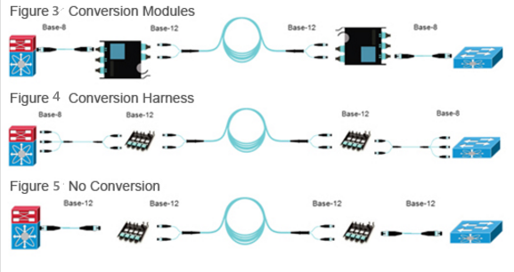
Based on a MPO system, migration from 10G to 40G to 100G seems to be a simple and easy deployment. Starting with a 10G configuration, a base 12F MPO backbone cable is deployed between the 10G switches. As discussed earlier, modules or harnesses are used at the end to transition from the 12F MPO to LC duplex. These breakout configurations enable connectivity into the switch.

transition to 40G
And when the switches migrate to 40G, the 10G module or harness is removed and should be replaced by a conversion module or conversion harness as shown in Figure 3 and Figure 4. Alternatively, an MPO adapter panel can be used. In any of these deployment options, the use of an MPO terminated jumper is needed to establish connectivity between the switches. For 100GBASE-SR4 networks all Figures 4-6 cabling is applicable.

Conclusion
To keep up with the path of future, MPO-based connectivity using OM3 and OM4 is the ideal solution for the data center, which makes the transition to 40/100G more easier and efficient. Fiberstore offers various types of 40GbE transceivers, MPO/MTP trunk cable, MPO/MTP harness cable, MPO/MTP cassette and other assemblies for your 40G network connectivity. For more information about our products, please contact us directly.

Tuesday, March 1, 2016

Laser-optimized Multimode Fiber – OM3 and OM4

How do I determine the type of fiber needed for my campus backbone? This is the question routinely asked by network designers. I must say, with many cabling options available in the market, it is a huge project to deploy a Gigabit Ethernet network—10GbE or 40/100GbE. As system engineers should not only decide which fiber type and the cabling infrastructure is perfect for their network, but the fiber counts. This article will briefly analyze the benefits of using laser-optimized 50µm multimode fiber in a Gigabit Ethernet application.
50µm Multimode Fibers Were Introduced 
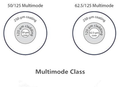
Before the advent of Gigabit Ethernet, choosing fiber type in a network design was quite easy. Standard 62.5µm multimode fiber (OM1) was used for any application up to 2000 m and network speeds up to 622 Mbps and single-mode fiber was used for anything else. But Gigabit and 10GbE changed these rules. Laser-optimized 50µm multimode fiber (like OM3 and OM4) was developed with increased bandwidth performance for 10GbE, and the fiber performance was included in the ANSI/TIA-568 Standard. Figure 1 provides a vivid impression on 50µm and 62.5µm multimode fiber.

Multimode fiber

Why Consider 50 µm Over 62.5 µm?
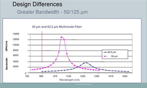
The major difference between 50µm and 62.5µm multimode fiber is the bandwidth. 50µm fiber is specifically designed to produce higher bandwidth values than 62.5µm at 850 nm, which enables the fiber to be used with lower cost 850nm VCSEL transmitters. Standard 50µm fiber has three times the bandwidth of standard 62.5µm fiber in the short wavelength operating window while some of the never laser-based 50µm fiber designs have 10-20 times the bandwidth of standard 62.5µm fiber (see in Figure 2). The most commonly used 50µm fibers on the market for Gigabit Ethernet is OM3 and OM4.

difference between 50µm Over 62.5µm

OM3 and OM4 Fibers
OM3 and OM4 fibers are essential components to the success of 10G optical connectivity, which are optimized for laser-based 850nm operation and have a minimum 2000 MHz•km and 4700 MHz•km effective modal bandwidth, respectively. 10G operation is supported on OM3 to 300 m and OM4 to 550 m compared to 100 m with CAT 6A copper cable. The laser-optimized fibers provide a migration path for supporting even higher data rates such as 16G and 32G Fibre Channel and 40/100G Ethernet where CAT 6/6A has no migration beyond 10G. OM3/OM4 laser-optimized 50µm multimode fiber for 10G optical connectivity in data center enables better transmission distance and performance when comparing with OM1 and OM2 fibers. For example, GP-10GSFP-1S is compatible Dell Force10 10GBASE-SR SFP+ transceiver. It required an OM3 cable to realize the link length of 300m.
As increased bandwidth requirements are called out in new installations, which have dictated a need to transition from cost-effective multimode systems to more costly single-mode systems to solve the problem of limited transmission distance in the existing infrastructure. However, compared with the expensive single-mode cabling, OM4 effectively provides an additional layer of performance that supports these applications at longer distances, thereby limiting the number of installations that truly require OS2 single-mode fiber. OM4 can even provide a minimum reach of 125m over multimode fiber within the 40 and 100GbE standards. For example, FTL410QE2C (compatible Finisar 40GBASE-SR4 QSFP+) covers a distance of 150m over OM4 cable.
Conclusion
When determining fiber types for a network application, a couple of key points should be drawn to help make the best decision. First, use the standards of each technology, do some analysis, understand the physical topology and the logical topology, then examine where you can save money. Last but not least, for distances less than 550 m, a laser-optimized multimode fiber may yield a price savings compared to a single-mode solution. Fiberstore provides a full range of multimode fibers including OM1, OM2, OM3 and OM4 multimode fibers. We offer these cables at a minimum price but with high quality. If you have any requirement of our products, please contact us directly.

Tuesday, February 23, 2016

Structured Cabling or Unstructured Cabling Solutions

40G network has replaced 10G lately and used worldwide, under this circumstance, 40G equipment like 40G transceivers and QSFP+ cables are required. Plan the cabling system in advance is the prerequisites to the designing of network system. The goal is to address current network requirements as well as accommodate future growth. There are two types of cabling solutions for 40G—structured cabling and unstructured cabling. This article will mainly introduced these two cabling solutions to you.
What Is Structured Cabling?
Structured cabling specified by the EIA/TIA TR42 committee, is the standardized architecture and component for communication cabling. In a structured cabling system, a series of patch panels and trunks are used to create a structure that allows for hardware ports to be connected to a patch panel at the top of the rack (see in Figure 1). A structured cabling system provides a flexible cabling plan to address the commonly performed tasks of moving, adding, and changing the infrastructure as the network grows.
structured cabling
What Is Unstructured Cabling?
Unstructured cabling occurs when optical links are deployed point to point or device to device with no patch panels installed in the link. In this situation, cabling pathways become congested with an entangled mess of two-fiber optical patch cords (Figure 2). Likewise, routing new patch cords in ceiling or floor trays all the way across a data center each time a new device is deployed is extremely inefficient.
Unstructured cabling
Structured or Unstructured Cabling System
As noted before, the difference between structured and unstructured cabling lies in the installation of patch panels. A good analogy for this is the electrical wiring in your home. When connecting appliances and devices, you require only a 5-foot connection to the closest electrical outlet. However, without an electrical outlet, all appliances would have to connect directly to the breaker or panel, requiring a cable of 200 feet or more. This approach would be inefficient and would become unmanageable as you add multiple appliances and devices throughout the home.
Unstructured cabling like above point to point connectivity method can’t satisfy people’s needs any more. Because it may appear some mistakes in an unorganized messy cabling infrastructure. Remove a single cable from a large tangled mess can cause stress on the other cables. This stress can lead to network errors in the hardware that are very difficult to trace. Therefore, structured cabling becomes a necessity as the infrastructure grows and as constant moves and changes reinforce the need for a reliable network that is also easy to troubleshoot.
40G Structured Cabling Components
Laser-optimized multimode fiber, compared with single-mode fiber has proven itself to be the cost-effective cabling methods for high-data-rate system like 40GbE network, which has become the dominant fiber choice. Optimized for 850-nm VCSEL transceivers, these 50-micron fibers (especially OM3 and OM4) provide optimum technical and economic solution and become the dominant structured cabling options for today’s data centers. QSFP+ transceiver (typically with a 12-fiber MTP connector) is the dominant transceiver used for 40G applications. Other essential components for 40G structured cabling include MTP trunk cables, MTP-LC harness/breakout cables, LC or MTP patch cables, MTP-LC cassette modules, MTP adapter panels and MTP rack mount holders.
Conclusion
When deploying a network system, it is important to plan a cabling system in advance. Structured cabling uses fiber termination connector panels that are connected through permanent links of optical cabling, which is more popular than unstructured cabling. Fiberstore supplies a wide range of fiber optic transceivers and MTP/MPO assemblies such as MPO/MTP trunk cables, harness cables, cassette module and adapters. We also provide cost-effective 40G products including 40G QSFP and 40G cables. To satisfy your unique demands, we support custom or OEM service as well. For more information, please contact us directly

Thursday, February 18, 2016

Multi-mode or Single-mode Optics for 40GbE Network

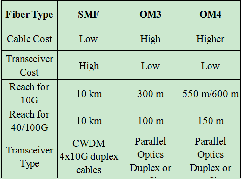
To back the changing and fast-growing bandwidth demands of data center, in 2010, the IEEE ratified 40 Gigabit and 100 Gigabit standards, known as IEEE 802.3ba. 40G and 100G Ethernet can be deployed using the same cabling systems today. Both single-mode (SMF) and multi-mode (OM3,OM4) were approved to be utilized in the standard. Multi-mode deploys parallel optics with MPO/MTP interconnects while single-mode fiber will employ serial transmission and use LC or SC connectors. Which cabling options designers should choose for their infrastructure. This article today will provide some practical suggestions to help you make a wise selection. Table 1 shows the comparison between SMF and MMF for 40/100 GbE Implementations.
table lists contrast between SMF and OM3,OM4
40GbE Over Multi-mode Fiber
40GbE and 100GbE over multi-mode optics use parallel optics at 10Gbps lasers, simultaneously transmitting across multiple fiber strands to achieve high data rates. Because of the multi-lane nature of these optics, 40GbE multi-mode optics use a different style of fiber cabling, known as MPO or MTP cabling. An MPO/MTP cable presents 12 separate strands of multi-mode fiber in a single ribbon cable. Just as 10GbE optics over multi-mode fiber, an OM3 or OM4 grade MMF is needed to cover longer distances for 40G network.
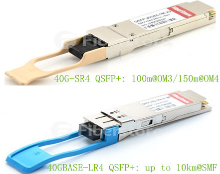
OM3 and OM4 MMF are laser-optimized fiber with a core size of 50/125 micron. These 50-micron fibers are optimized for the 850nm transmission of VCSEL-based transceivers. These two fibers have different bandwidths, which results in different achievable lengths for the same transceivers. OM4 fibers, according to the TIA-492AAAD, have higher network reliability and increased design flexibility allowing links with a reach of 150 meters. The IEEE 802.3ba standard specified OM3 fiber with a maximum reach of 100 meters. Take Cisco QSFP-40G-SR4 QSFP+ as an example, it can support a distance of 100m and 150m over OM3 and OM4, respectively. The following image shows a 40G-SR4 and 40GBASE-LR4 QSFP+.
two types of 40G QSFP+ module
Since we can deploy both OM3 and OM4 MMF for our 40G infrastructure, which one is more suitable? In fact, some senior engineers say that installing either OM3 or OM4 cabling in the data center largely depend on length requirements. They determined that OM4 fiber would substantially extend the reach of next generation networking within the data center and it is able to achieve this greater reach because of its greater EMB over OM3 fiber. OM4 optical fiber enables 40/100G Ethernet to reach an additional 60% of the links in the core-to-distribution and in the access-to-distribution channels when compared to OM3. This should lead to faster market acceptance of 40G/100G Ethernet and OM4 fiber.
40GbE Over Single-mode Fiber
40GBase-LR4 optics use the same multi-lane technology as SR4 optics using four strands for transmit and four strands for receive. But with one exception. Instead of using a single fiber strand for each lane, WDM technology is used to multiplex all four transmit lanes onto one strand of fiber and all four receive lanes onto another single strand of fiber, allowing any existing single-mode fiber installation to be used. Because of this, standard LC (for QSFP modules) or SC (for CFP modules) connections are used, allowing for an easy upgrade from a 10GbE connection. The channel cost for 40GBASE-LR4 is much higher than SR4 optics, which is the main factor that limits its popularity. However, 40GBASE-LR4 like Cisco QSFP-40G-LR4 can reach up to 10km.
Conclusion
After going through this article, do you have any idea of choosing which cabling for your 40G network. If you have tight budget and cover a short transmission distance, laser-optimized multi-mode cabling would be the prefect choice. But if you prefer to deploy a high-density long-reach network, single-mode cabling will suit you better. Fiberstore manufactures a large variety of 40G transceivers and cables. You can find what you need here. Please contact us if you are interested.

Monday, February 8, 2016

How to Select the Basic Materials of the LAN

Installing or designing network may pose a challenge as there are multiple optical solutions that meet the same specification or requirement. But by understanding the basic optical components and the specific performance requirements, you will be able to generate a cost-efficient bill of materials for your project. Thus before picking any products for your infrastructure, you must read this article.
Fiber Type
There are two basic fiber types: single-mode and multi-mode. Multi-mode fiber is graded by OM (optical multi-mode), the higher the OM grade, the better bandwidth performance you can expect. And it comes in both 50μm and 62.5μm core sizes with 50 μm multi-mode available in both standard (OM2) as well as a laser-optimized version (OM3/OM4). Single-mode are graded by OS (optical single-mode) and can run at OS1 and OS2, as described in TIA-568 C.3. Keep the consistency within your network is critical for long-term performance, therefore you shouldn’t mix new fiber type or performance with your old plant.
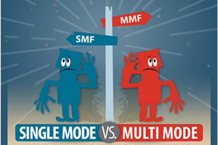
single-mode vs.multi-mode fiber transceiver
In addition, the cost of the components should be considered. The transceiver associated with single-mode fiber are more expensive than those for multi-mode. For example, the price of JG661A (compatible HP 40GBASE-LR4/OTU-3 QSFP+ transceiver) is much higher than JG325B (compatible HP 40GBASE-SR4 QSFP+ transceiver). The decision must be made to balance the performance and the cost. Single-mode system will provide for future expansion, yet multi-mode fiber is only for today and the near future. To sum up, single-mode fiber operate better at long reach while multi-mode fiber is ideal for short reach, choosing single-mode or multi-mode depends on your networks needs.
Termination Method
Deciding on a termination methods is typical affected by many factors. If your biggest concern is time, no epoxy/no polish connectors are probably your best choice. The fiber end faces are factory polished and easily installed with a tool kit. This types of termination method allows you to perform terminations quickly, but the cost is usually higher than that of epoxy and polish connector.
If your biggest concern is cost. epoxy and polish connectors might be a good fit because of their low initial price. This type of termination need considerable time to learn how to properly hand-polish connectors that meet specification, and it requires a large workspace to lay out the polishing papers, polishing pucks, epoxy, etc. If your work environment or network condition is not allowed, it is advisable not to select this method.
Fusion Splicer or Optical Connector
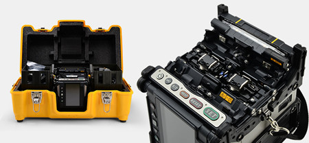
Keep in mind that whether to choose fusion splicing or a connector for your network will always need an experienced installer under adequate training. Fusion splicer, as we all know, is very expensive. If your company do not own one, it can be a large investment to make and you need to order the correct splice tray for your hardware and heart-shrinks to keep your splices intact. But if you already have a fusion splicer, fusion-spliced pigtails might be the right choice for you that can provide high quality results and easy to use in areas. The following picture shows a Fujikura FSM-80S Core Alignment Fusion Splicer.
Fujikura FSM-80S Core Alignment Fusion Splicer
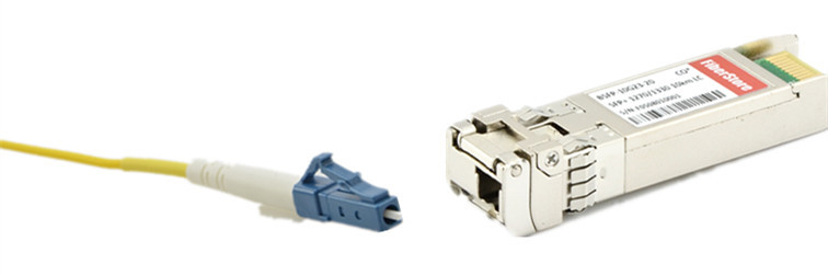
Specifications, density, electronics interfaces and existing plant often drive connector choices. LC connector is favored for its maximum density and room-saving. It is also available in duplex from, which allows you to manage polarity by simply reversing the connector via a duplex clip. SC connectors feature an easy push/pull locking mechanism and are available in simplex and duplex forms. ST compatible connectors have a spring-loaded bayonet locking system that helps them stay in place but are only available in simplex versions.
Hardware
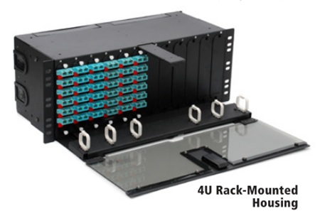
To determine the type of hardware you need, take into consideration the space that will be utilized for the network. If you are installing inside of a closet or other cramped quarters and need low density, wall mountable hardware is the best selection as it does not take up a lot of room. If racks are already in place, or if there is enough room to install them, rack-mount hardware is the best selection because it is sturdy and easy to access.
Rack-mount housing
Additional Information
Designing a network may be a big project as you should take a lot of things into consideration. To make sure the high performance of you network, please think about all the aspects that I have written in this text. What’s more, there are three basic categories for cable: indoor, outdoor and indoor/outdoor. The types of cables you have to choose for your infrastructure depend on where the cables will be run. Fiberstore supplies a whole variety of optical equipment including fiber optical cables, optical transceivers, fusion splicer and optical connectors. Come to us to help your data transmission initiatives for future proof.