Network speeds like 40G and 100G Ethernet have already become the mainstream in data centers, and the industry is still working collaboratively on the next-generation development for higher density and faster speed. Multimode fibers, for example, are treated as the cost-effective solutions for short-reach optical interconnects. OM5 fiber, certificated in 2016, is know as the wide band multimode fiber (WBMMF) designed to carry signals over short wavelength (850nm to 950nm). Many enterprise IT and data center managers nowadays are adopting single-mode fiber system or OM4 cabling in the network infrastructure. Will OM5 MMF be a good alternative for 40G/100G network system? This article will provide the detailed information about OM5 fibers, and make a clear comparison between OM5, OM4 MMF and single-mode fiber cables.

Is OM5 WB MMF Fiber A Good Solution for Data Centers?
No exact answer can be provided here as OM5 MMF is still a new product in 2017.
OM5 MMF fiber has the same geometry as OM4: 50 µm of core size and 125 µm of cladding, which make it fully compatible and intermateable with OM3 and OM4 cabling. OM5 fiber specifies a wider range of wavelengths between 850 nm and 953 nm. The additional specifications of effective modal bandwidth and attenuation at 953 nm is identical to specification of OM4.
It was created to support Shortwave Wavelength Division Multiplexing (SWDM), which is one of the new technologies being developed for transmitting 40 Gb/s, 100 Gb/s, and beyond. With the use of SWDM technology, it is desirable to reduce parallel fiber count by at least a factor of four to allow continued use of just two fibers (rather than eight) for transmitting 40 Gb/s and 100 Gb/s and reduced fiber counts for higher speeds.

The 40/100GbE expected maximum operational distances of OM5 fiber is displayed in the above table. OM5 fiber can support longer distance of 440m for 40G SWDM, and 150m for 100G SWDM system.
How Does OM5 Differ From 50 µm Laser Optimized OM4 Fiber?
Wavelength—OM5 WB MMF is intended for operation using vertical-cavity surface-emitting laser (VCSEL) transceivers across the 846 to 953 nm wavelength range, while OM3 and OM4 50 micron laser optimized multimode fiber, whose bandwidth diminishes rapidly above the 850 nm operating wavelength.
Effective Modal Bandwidth (EMB)—the best system performance is achieved by a combination of low chromatic dispersion and high EMB. OM5 EMB values are specified as following at both 850 and 953 nm.
• EMB>4700 MHz.km at 850 nm
• EMB>2470 MHz.km at 953 nm
• EMB>2470 MHz.km at 953 nm
However, the OM3/OM4 EMB values are 2000/4700 MHz·km at 850nm. We can see that the OM5 EMB is lower at 953nm compared to 850nm.
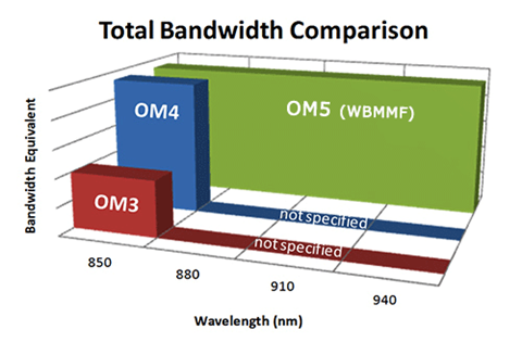
More capacity—OM5 is designed and specified to support at least four WDM channels at a minimum speed of 28Gbps per channel through the 850-953 window. Compared to OM4, it is specified only to work at the 850 nm window.
Even though signals illuminating at wavelengths greater than 850 nm will be transmitted by OM3 and OM4, the absence of specification and test data outside the 850 nm window makes it difficult to predict and model the performance of short wavelength-based WDM systems. In conclusion, OM5 is specifically designed to carry at least four channels between 850 nm and 953 nm, and guarantees that capacity increases four times.
• OM5 carries at least 4X more capacity than OM4 over a meter of fiber.
• OM5 carries 5.7X more capacity than OM3 over a meter of fiber.
• OM4 only carries 1.4X more capacity than OM3 over a meter of fiber.
• OM5 carries 5.7X more capacity than OM3 over a meter of fiber.
• OM4 only carries 1.4X more capacity than OM3 over a meter of fiber.
Why Should I Consider OM5 Over Single-mode Fiber?
Cost-effective solution—even thought the costs of single-mode transceivers have declined considerably over the past few years, the delta relative to multimode remains approximately 50%. OM5 MMF fiber allows for more cost-effective migration to transmission speeds up to 400Gbps utilizing lower-cost optics as opposed to single-mode fiber.
Easy management & installation—in 40G/100G network, multimode connectivity together with MTP/MPO systems makes for a more user-friendly solution for data centers as well as building and campus backbones, especially in cable installation, troubleshooting, cleaning, and overall maintenance.
Seamless Migration to 400Gbps—OM5 multimode fiber delivers higher value to network owners for distances up to 500m (for data rates up to 40Gbps), and allows for smooth migration to 400Gbps for distances up to 150m. For distances beyond 500m, single-mode fiber is recommended.
Conclusion
OM5 MMF fiber has a long way to go even though it is being presented as a potential next-generation option for data centers. So far, I don’t see any tempting reasons to recommend OM5 relative to OM4 cables or single-mode fibers for 40G/100G data centers. But FS.COM will keep you upgraded with the latest development of wide band multimode fibers. For more about our 25G/40G/100G optical solutions, please directly visit our website.