
Pluggable Optic modules are typically used in systems to leverage the rapid long data transmission distance of which fiber optic networks are capable. To realize the maximum distance, network designers must ensure that the integrating optical networks are robust and aware of the knowledge of the whole system—the types of optical modules and the electrical and optical standards for which the optical module is designed, and the host transceiver features that are required to transmit and receive data through an optical system. It seems to be troublesome process. So today’s article is intended to help designers overview the available options in the pluggable optical module market, along with the optical patch cables that must be considered when making design choices.
Pluggable Optical Modules Overview
When a designer looks at implementing an optical interface, several choices need to be made based on the protocol and application. Take optical transceiver module as an example, to select a suitable transceiver module, you need to take the following factors into consideration—types of optical modules, different form factors, features, electrical and optical specifications, and lane width, etc. Figure 1 shows several pluggable optic transceivers. Can you recognize them?
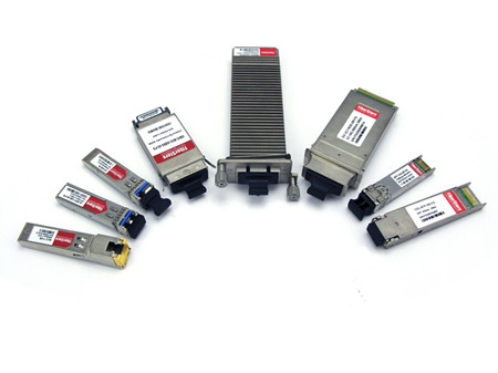
Optics have a long history of use in the telecommunications sector. As a result, there is a wide variety of form factors that are available for optical modules. To simplify the discussion, this article focuses on the current set of optical modules utilized for 10G, 40G, and 100G Ethernet, though many of the topics translate directly to OTN or other standards. These Ethernet rates can be supported by a variety of electrical lane widths (usually one, four, or ten lanes), which in turn determine the electrical line rates. For example, either four lanes of 3.125 Gb/s or a single lane of 10.3125 Gb/s can support 10G Ethernet; similarly, either ten lanes of 10.3125 Gb/s or four lanes 25.78125 Gb/s can support 100G Ethernet. The current crop of high-end optical modules leverages a base rate of 10.3125 Gb/s, for 10G, 40G, and 100G Ethernet in one, four, or ten lanes. Popular optical modules are available that support each of these widths at this rate: SFP+ or XFP for a single lane, QSFP+ for four lanes, and CFP for ten lanes. Take XFP-10GLR-OC192SR as an example, it is XFP compatible 10GBASE-LR/LW transceiver with a maximum data rate of 10.3125Gbps over single lane. Module type is constrained only by its form factor and pinout, supporting a variety of electrical and optical standards. This large field of choice adds to the complexity of selecting the correct parts for design into a system.
Impact of Optical Fiber on a System
One common difference between modules is the length and type of fiber a module can drive. SFP+ makes itself a good example for examining the options. 10G Ethernet defines a number of optical interfaces (SR, LR, LRM, and ER) along with other industry adopted standards (ZR and DWM) that specify the optical wavelength and the length and type of optical fiber that can be supported. Each element of this selection has a different impact on the link performance. For example, 10GBASE-SR (e.g. SFP-10GB-SR) uses an 850nm wavelength and can support up to 300m of 50µm multimode fiber while 10GBASE-LR uses a 1300nm wavelength and can support 10 km of single mode fiber.
Fiber Optic Patch Cable Overview
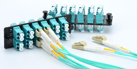
Choose a fiber optical cable is largely on the selection of multimode and single-mode fiber. The differences between multimode fiber and single-mode fiber are important. Single-mode fiber consists of a single strand of fiber that the data is transmitted across. Multimode fiber is composed of multiple strands of fiber bundled together, where light can pass across each strand. In either case, an effect known as dispersion can impact the fidelity of the transmit signal. As the signal passes through the fiber, the distribution of wavelengths of light that contain signal content are interacted with in slightly different ways, some wavelengths experiencing more delay or varying degrees of attenuation. The impact of this optical dispersion to the waveform is distinctly different from how copper impacts electrical signals. As a result, high levels of optical dispersion require special circuitry to compensate for, typically in the form of a feed-forward equalizer (FFE) in conjunction with the standard DFE and CTLE structures used for electrical channels. Figure 2 shows LC multimode fiber optic patch cable plugging in adapter panel.
While both single-mode and multimode fiber introduce some dispersion, the single-mode has the advantage that very little dispersion occurs per unit length compared to multimode fiber, leaving loss as the primary contributor to signal degradation at the far end of the link. The amount of dispersion introduced in multimode fiber varies depending on the laser wavelength. At 850 nm (used for 10GBASE-SR), very little optical dispersion is introduced over the maximum 300m of fiber. Comparatively, at 1300 nm (used for 10GBASE-LRM), far more dispersion is introduced—enough that it needs to be compensated for after the signal is translated into the electrical domain.
Conclusion
Fiber optics is becoming a standard part of today's high-bandwidth landscape. Designers using optics are faced with a wide variety of choices of implementation rates, form factors, optical standards, electrical standards and the trade-offs between them. Knowing how the features of a given optical module impact the rest of the system is an advantage that cannot be ignored. Fiberstore is dedicated to supporting a wide variety of optical interfaces at today's 10Gb/s standards and beyond. We provide pluggable optical modules from 1G SFP modules to 100G CFP2 modules, as well as offering a full range of optical cables. For more information on how to implement optical interfaces, you are welcome to contact us.
Thank you for sharing the information.
ReplyDeletePassive Networking
Structured Cabling
Thanks for sharing structured cabling companies in dubai
ReplyDelete