Sunday, February 26, 2017

QSFP28 100G Transceivers & DAC Guide

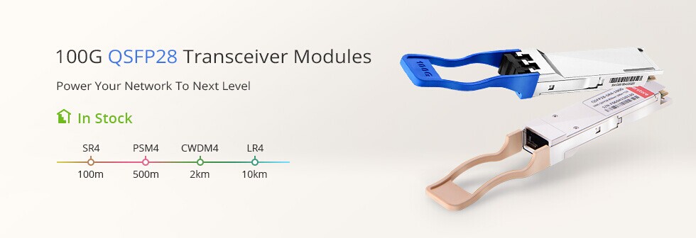
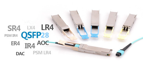
Telecom industry embraces the prosperity of 100G optics market in 2017. With such a bright future, fiber optic market attracts a wide attention, and many vendors want a piece of the pie. The 100G optics like the CFP, QSFP28 modules and cables are varied in different standards. QSFP28 optics, along with its compact size and reliable performances, gradually becomes the mainstream form factors of the 100G optics market. QSFP28 modules come in different standards (LR4, SR4, PSM4, CWDM4), and the QSFP28 AOC and DAC cables are also available for 100G systems. Which one is ideal for your 100G network? This article attached with the detailed information of all the 100G optics, will blew your mind.
QSFP28 100G
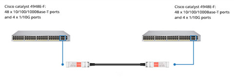
QSFP28 DAC Inside Rack: <5 m
QSFP28 passive DAC cables are launched to decrease the cost of 100G systems, which provide a cost-effective I/O solution for 100GbE connectivity within 5 m. QSFP28 to QSFP28 DACs and QSFP28 to 4x SFP28 DACs are the two common types of the QSFP28 DAC cables. QSFP28 to QSFP28 direct attach cable is usually used inside racks with QSFP28 connectors terminated on each end. QSFP28 breakout DACs can achieve 25G to 100G transmission with a QSFP28 connector on one end and 4 SFP28 connectors on the other end. If your 100GbE deployment is within 5m intra racks, the QSFP28 DAC is ideal for you.
QSFP28 AOC: Up to 100 m
The QSFP28 AOC is a cost-efficient, four-channel optical transceiver that conforms to the QSFP28 multi-source agreement. It is capable of delivering 100-Gbps data rates over four lanes of 25 Gbps with a reach of up to 100 m, maximum. Just as the QSFP28 DAC, QSFP28 AOC cable also comes in two types—QSFP28 to QSFP28 AOC and QSFP28 to 4SFP28 AOC. The former one is best fit for 3-20 m, and QSFP28 breakout can support a link length of up to 100 m. The QSFP28 AOC supports InfiniBand EDR and 100 Gigabit Ethernet (100GBase-SR4) transmission speeds and is best for close-range, high-speed transmission in data center networks, such as between servers and server racks.
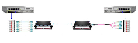
QSFP28 SR4 Close Range: 5-100 m
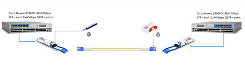
For 100GbE cabling with multimode fiber between switches, QSFP28 SR4 with 12-fiber OM4 MTP fiber cable is the perfect choice. It can support reaches up to 100 m over OM4. The 100Gbase-SR4 QSFP28 module achieves four lanes of 25G dual way transmission over eight fibers. QSFP28 SR4 module is compliant with 100GBASE-SR4 standard certificated by IEEE. It is the firstly published 100G standard to support short distance over multimode fibers. Many vendors offer the compatible QSFP28 SR4 optics with good quality and high reliability. FS.COM is one of the best that can provide the test-assured OEM optics with great customer feedback. All the products included in the below chart are provided at FS.COM.
100G QSFP28 optics
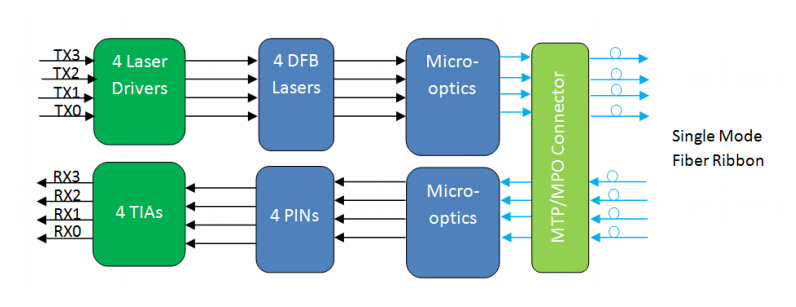
QSFP PSM4 Between Switches: 100 m-500 m
For 100G connectivity, if the reaches are beyond 100m but less than 500m, you can use the QSFP PSM4. Unlike the QSFP28 SR4 optics (by IEEE), PSM4 standard is published by MSA. 100G PSM4 QSFP28 is designed to support a transmission distance up to 500 m over MPOI single-mode multi-fibers.
QSFP CWDM4 Mid-Reach: 500 m-2 km
Reaches less than 2 km are usually called mid-reaches. QSFP28 CWDM4 is the module designed to meet the mid-reach requirements. MSA published 100Gbase-CWDM4 standard for QSFP28 over single-mode up to 2 km over through duplex LC interface. It uses WDM technologies like 100Gbase-LR4. But the transmission distance is shorter and the cost is much lower.
QSFP28 LR4 Long Span: ≤10 km
For long distance transmission between two buildings, the IEEE standard 100Gbase-LR4 is being used in QSFP28 form factor which is known as QSFP-100G-LR4 module. Unlike QSFP-100G-SR4 modules, QSFP-100G-LR4 uses the WDM technologies for four 25G lanes transmission. The four 25G optical signals are being transmitted over four different wavelengths. It has a duplex LC interface for 100G dual-way transmission. 100Gbase-LR4 QSFP28 can support transmission up to 10 km over single-mode fiber. But one problem is that the cost of QSFP28 LR4 is very high now. What’s worse, you would need the EDFA to offset the link loss.
Conclusion
To achieve higher data-rate transmission speed, new network design will work to bring us closer to meet the needs of a Big Data future. This article concludes the features of existing QSFP28 100G products on the market. After going through the whole passage, you must know which one is ideal for your network.

Thursday, February 23, 2017

100G QSFP28 PSM4 to Address 500m Links in Data Center

100G QSFP28 PSM4 optics is a type of 100G optical transceiver that provides a low-cost solution to long-reach data center optical interconnects. 100G PSM4 (parallel single-mode 4 lane) standard is mainly targeted to data centers that based on a parallel single-mode infrastructure for a link length of 500 m. Compared with the hot-selling 100GBASE-SR4 and 100GBASE-LR4 optics, 100G QSFP28 PSM4 recently wins the popularity among the overall users. This article will provide a complete specification of the 100G QSFP28 PSM4 transceiver and explain the reason why people would need QSFP28 PSM4.
QSFP28 module
QSFP28 PSM4—A Low-Cost but Long-Reach Solution
100G QSFP28 PSM4 is compliant with 100G PSM4 MSA standard, which defines a point-to-point 100 Gb/s link over eight parallel single-mode fibers (4 transmit and 4 receive) up to at least 500 m. PSM4 uses four identical lanes per direction. Each lane carries a 25G optical transmission. The 100G PSM4 standard is now available in QSFP28 and CFP4 form factor. Table 2 shows the diagram of the 100G QSFP28 PSM4 Specification. 100G PSM4 is a low-cost solution. Its cost structure is driven by the cost of the fiber and the high component count. FS.COM offers the Cisco compatible 100G QSFP28 PSM4 at US$750.00.
diagram of QSFP28 PSM4
As you can see in the above image, 100G QSFP28 PSM4 transceiver uses four parallel fibers (lanes) operating in each direction, with transmission distance up to 500 meters. The source of the QSFP28 PSM4 module is a single uncooled distributed feedback (DFB) laser operating at 1310 nm. It needs either a directly modulated DFB laser (DML) or an external modulator for each fiber. The 100GBASE-PSM4 transceiver usually needs the single-mode ribbon cable with an MTP/MPO connector.
Why Do We Need 100G QSFP28 PSM4?
100G PSM4 is the 100G standard that has been launched by multi-source agreement (MSA) to enable 500m links in data center optical interconnects. But as we all know, there are several popular 100G interfaces out there on the market, such as QSFP28 100GBASE-SR4, QSFP28 100GBASE-LR4, QSFP28 100GBASE-CWDM4, and CFP 100GBASE-LR4, etc. So with so many options, why do we still need 100G QSFP28 PSM4?
To better help you make up your mind, you need to figure out the following questions:
Q1: What are the net link budget differences between PSM4, SR4, LR4 and CWDM?
Table 3 displays the detailed information about these 100G standards.
 100GBASE-PSM4100GBASE-CWDM4100GBASE-SR4100GBASE-LR4
4-wavelength CWDM multiplexer and demultiplexerNo needNeedNo needNeed
ConnectorMPO/MTP connectorTwo LC connectorsMPO/MTP connectorTwo LC connectors
Reach500 m2 km100 m10 km
Note: the above diagram excludes the actual loss of each link (it is the ideal situation). In fact, WDM solution are at least 7 db worse link budget than PSM4. For a 2 km connectivity, a CWDM module will have to overcome about 10 db additional losses compared to PSM4. And the 100G LR4 optics at 10 km is 12 db higher total loss than PSM4.
Q2: What power targets are achievable for each, and by extension what form factors?
According to the IEEE data sheet, the WDM solutions cannot reasonably fit inside QSFP thermal envelop, while PSM4 can fit inside the QSFP thermal envelope. That means you would need the extra power for the WDM solution of your network. But if you use the QSFP PSM4, this won’t be a problem.
All in all, a 100G QSFP28 PSM4 transceiver with 500m max reach is a optional choice for customers. Because other 100G optics are either too short for practical application in data center or too long and costly. QSFP28 PSM4 modules are much less expensive than the 10 km, 100GBASE-LR4 module, and support longer distance than 100GBASE-SR4 QSFP28.
Summary
QSFP28 PSM4 is the lowest cost solution at under one forth the cost of either WDM alternatives. 100G QSFP28 PSM4 can support a link length of 500 m, which is sufficient for data center interconnect applications. 100G QSFP28 PSM4 also offers the simplest architecture, the most streamlined data path, higher reliability, an easy upgrade path to 100G Ethernet.

Wednesday, February 15, 2017

Use Case for 10G/40G Switch-to-Switch Interconnect

In addition to 10 GbE, the telecom market nowadays is also actively deploying 40 GbE connections to support server connectivity, the typical use case is switch-to-switch interconnects. In fact, copper cables is used in some special cases, primarily for switch-to-switch short-reach connections. However, with the majority of 40 GbE connections being optic fiber-based, fiber optic cables, especially the MTP/MPO cables are widely deployed. From a cable plant standpoint, continued investment in fiber parallel-optic technologies will position the physical infrastructure for eventual migration to 100 GbE and beyond. This article will provide available physical cable technologies for 10G and 40G connectivity.
10 GbE Cable Solutions
Higher transmission speeds require us to implement new cable technologies to optimize our 10 GbE infrastructure:
  • 10GBASE-T.
This connection over unshielded or shielded twisted-pair cables can support distances over 100 meters (330 feet) with Category 6a cable, 55 meters with Category 6 cable, and 45 meters with Category 5e cable. Category copper cables like cat5e and cat6 cable reel are the most commonly used types. We are using limited 10GBASE-T to serve the high-density connectivity within racks. 10GBASE-T has some cost advantages but it also consumes more power than optical technology.
  • Small-Form-Factor Pluggable (SFP+) direct-attach cables.
These twinaxial cables support 10 GbE connections over short distances of up to 7 meters. Some suppliers are producing a cable with a transmission capability of up to 15 meters.
Cisco SFP+ DAC cable
Figure 1 shows a simple and economic sulution for you, just connecting two Cisco Catalyst 4948E-F Switches with a 10G SFP+ Passive Direct Attach Copper Twinax Cable.
  • MPO cabling.
We are using this technology to simplify cabling and reduce installation cost because it is supported over SFP+ ports. One trunk cable that we use can support 10 GbE up to 90 meters and provides six individual connections. This reduces the amount of space required to support comparable densities by 66 percent. The trunks terminate on a variety of options, providing for a flexible system.
10G MPO cabling
Figure 2 shows the Interconnection for 10-Gbps Connectivity with MTP Multimode Fiber Optic Trunk Cable, 12 Fiber, Polarity B.
We use an MPO cable, which is a connectorized fiber technology comprised of multi-strand trunk bundles and cassettes. This technology can support 1 GbE and 10 GbE connections and can be upgraded easily to support 40 and 100 GbE parallel-optic connections by simply swapping a cassette. The current range for 10 GbE is 300 meters on OM3 MMF and 10 kilometers on SMF.
40GbE Switch-to-Switch Interconnects
A 40 GbE switch-to-switch interconnect can use one of three methods.
  • QSFP+ transceivers and MMF MPO trunks.
This configuration must use a Method B polarity MPO trunk.
  • Long-range QSFP+ transceiver and standard 2-strand SMF connections.
40G long-reach connectivity with SMF
Figure 3 shows two 40G QSFP+ transceivers connected by a single mode LC cable. This configuration is used where switch-to-switch interconnects span between data centers or buildings within a campus.
  • Active optical cable.
This is a pre-terminated parallel-optic solution which incorporates a 12-strand MMF bundle connected on each end with a QSFP+ transceiver. This type of cable is available in standard lengths up to 100 meters. This configuration is used for 40 GbE connections that span rows within the data center.
Conclusion
The existing 100Mbps and 1GE connections no longer support growing business requirements, so here comes the era of 10G and 40 GbE data center fabric design. The new fabric will reduce data center complexity and increase our network agility to meet growing data center needs. Today’s article offer the suitable fiber optic solutions for 10G/40G switch to switch interconnects. For more information about the products mentioned above, please visit our site.

Tuesday, February 7, 2017

Deciphering Male and Female RJ45 Connector

Many people think that RJ45 to RJ45 connectors are the same as the modular plugs or jacks, but they’re wrong. In most cases, the term plug technically refers to the cable or male end of the connection while the term jack refers to the port or female end. If you have had a misunderstanding about these concept, you probably have experienced problems that were extremely difficult to resolve in your network. Therefore this article will have a brief introduction to the male and female RJ45 connectors.
RJ45 Pinout
RJ45 connector stands for registered jack 45, is most commonly seen with bulk Ethernet cables and network cables. This registered jack specifies the physical male and female connectors as well as the pin assignments. Before we start with the discussion of the male and female RJ45 connector for modular connectors, it is good to know how pins are numbered on RJ45 connectors.
Two standard RJ45 pinouts define the arrangement of the individual eight wires needed when attaching connectors to a cable—the T568A and T568B standards. Both follow a convention of coating individual wires in one of five colors—brown, green, orange, blue and white—with certain stripe and solid combinations.
Following these color scheme is essential when building cables to ensure electrical compatibility with other equipment. T568B has become the more popular standard. The table below summarizes this color coding.
T568B T568A color coding
RJ45 cables using RJ45 to RJ45 connectors and cat5/cat6 twisted pair cabling is easy to construct using the correct tools. In particular, RJ45 connectors and cabling standards are simplicity itself as RJ45 only uses four of the eight pins on the connectors. Pins 1 & 2 transmit data, whilst pins 3 & 6 are used to receive data when used in an Ethernet configured data port.
Male and Female RJ45 Connector
RJ45 connector as the modular connector, has gender: plugs are considered as male, while jacks or sockets are considered to be female. Modern Ethernet cables feature small plastic plugs on each end that are inserted into RJ45 jacks of Ethernet devices.
Plugs are used to terminate loose cables and cords, while jacks are used for fixed locations on surfaces such as walls and panels, and on equipment. Other than telephone extension cables, cables with a modular plug on one end and a jack on the other are rare. Instead, cables are connected using a male-to-male adapter, which consists of two female jacks wired back-to-back.
RJ45 male to female connector
The scheme above shows the exact pin numbering on both male to male and RJ45 female to female connectors. All other modular jacks start counting at the same side of the connector. In the wiring diagrams with modular jacks on this site, we prefer to use a picture of the jack upside down, with the hook underneath.
Female Connector (Jacks) and Male RJ45 Connector (plugs)
Jacks and plugs have very similar packaging even though the functions that they perform are not similar at all. According to different applications, it comes in a wide range of different types from modular connectors and plugs (phone jacks, computer and Ethernet jacks etc.) to Internet connections and electronic components.
Telephone jack, or female to female RJ45 connector, is a very type of modular connector. This small unit is connected to a telephone cord which then transmits a telephone analog signal from a special phone outlet placed on a wall, desk or cubicle to the actual phone unit. An Ethernet jack looks much like a regular phone jack, but it is slightly wider. This port can be used to connect your computer to another computer, a local network, or an external DSL or cable modem. The following image shows the toolless cat5e Keystone Jack.
cat5e toolless Keystone Jack
As noted before, male plugs are used to terminate loose cables while female jacks are used for fixed locations. In other words, appliances have cords ending in a male plug, which is fitted into the female outlet. FS.COM RJ45 modular plug use on solid or stranded conductor cat5e cable. These modular plugs are manufactured from polycarbonate to withstand everyday wear and tear, and the contacts are 50 micron gold for optimum signal transmission.
The Common Issue With RJ45 Connectors
A male connector or plugs can be inserted snugly into a receptacle ( female connector ) to ensure a reliable physical and electrical connection. Some RJ45 plugs utilize a small, bendable piece of plastic called a tab to help form a tight connection between a cable and a port on insertion. But it is also the problem of the connector when it snags on another cable. The locking tab is prone to breaking.
Here I’d like to list some tricks to avoid this: Buy the connectors with the locking tab curved down so it avoids the snagging. If you can’t find the cleverly designed connectors use boots to avoid snapping the tabs. Use a good quality crimping tool that doesn’t press on the tab when you crimp the connector.
All in all, crimping a RJ45 to RJ45 connector is not easy. The operation requires dexterity attention and training. If you want to make your life easier, you can use wire guides that come with some packages. Practice a lot and you won’t need the guides.

Saturday, February 4, 2017

Understanding Bulk Ethernet Cable: Stranded or Solid Ethernet Cable

There are a dizzying number of bulk Ethernet cable type available on the market, corresponding to a array of standards detailing the configuration and performance specification needed to support the increasingly faster data rates and larger bandwidths of incoming technologies. Of which stranded and solid Ethernet cables are the commonly used cable types when purchasing bulk Ethernet cable. These two different types refer to the internal conduction inside the bulk Ethernet cable. Today’s article provide the detail information about these two copper network cables.
Stranded and Solid Ethernet Cable
Stranded Ethernet cable has multiple smaller strands of wires that are twisted together to form a single conductor. And a solid Ethernet cable is just fabricated with a single solid strand of copper for each of the 8 conductors. Figure 1 shows the inner structure of the stranded and solid Ethernet cable.
stranded or solid ethernet cable
From the above picture, we can see that each of the conductors inside a solid Ethernet cable is made up of a single, solid conducting wire with diameters between 22 and 24 AWG. Take cat6 bulk cable as an example, it employs the larger 23 AWG copper wires, which makes it better suited to new and emerging fast Ethernet applications (than cat5 bulk Ethernet cable). However, owing to the fragility of their conducting wires, the solid Ethernet cables are well-packed inside a strong outer sleeves that resists bending making them less flexible and not well suitable to normal everyday use in connecting work area component.
However, stranded Ethernet cable is the one that we most often work directly with. Unlike the solid Ethernet cable, the stranding of the wire conductors serves to protect them, and provide stranded cables their flexibility. For a given conductor length, the more times each strand twists around the central conductor, the better the protection and greater the overall flexibility of the cable. Because of their internal difference, each of the cable types might be suitable for a specified situation.
Choosing for Backbone and Horizontal Cabling
Installing any bulk Ethernet cable type (solid or stranded Ethernet cable) into a building’s structure should be well managed by keeping long-term applications in mind. Solid Ethernet cabling with its superior electrical performance and longer runs makes it more suitable for permanent building installations. Additionally, its stability over higher frequencies means that longer time periods are possible between cable reinstallations, and its comparative frailty is not a problem when it is protected from damage by the building itself. Since solid Ethernet cable is most often used for these permanent cabling applications, it often referred to as network cable.
For horizontal cabling, solid Ethernet cables are also used spanning the distances between telecommunications rooms and work areas. In addition to performing better over long distances and at higher frequencies, the single, larger conducting wires of solid cables are much easier to terminate than the multiple fine wires of stranded conductor cables. Also, the relative stiffness of solid cable makes it preferable for use with punch down connectors on the backs of wall jacks. In contrast, the softness and flexibility of stranded Ethernet cables make working with punch down connectors or IDCs (Insulation Displacement Connectors) very difficult.
In conclusion, there is very little difference between the electrical performance of solid and stranded cables for very short lengths (below 10 meters). In modern hierarchical wiring schemes, the length limitations of stranded cables are easily met (3 m, or 9.8 ft), and the increased flexibility and durability of stranded cables make them perfectly suited for interconnecting work area outlets with workstation PCs and other end-user devices.
However, solid cables are far too fragile for frequent bending and handling, and far too difficult to manage in connecting closely spaced components. The conductors inside a stranded cable are protected by the wire strands surrounding them, so that very little of the conducting surface area is exposed to damage if the cable is accidentally cut or smashed, and the conductor is not weakened by repeated flexing and bending. Without this protection, the conducting surfaces within a solid-conductor cable are more susceptible to nicks or other irregularities that affect transmission performance and often accompany their early demise.
Conclusion
As we move toward increasingly faster Ethernet systems, the copper transmission medium would require increasingly faster frequencies and data rate. For solid and stranded cables, the differences seen in electrical activity are very little. FS.COM offers a full range of bulk Ethernet cables including the cat5 bulk cables, cat6 bulk cables, cat7 bulk cables, and copper cable assemblies. If you have any interest, please contact us.