Thursday, December 29, 2016

Why Should We Keep Fiber Optic Connectors Clean?

Fiber optic technicians are aware that dirty connections can cause attenuation, but they may not realize that it can also cause bit errors or slowdown of the network. Therefore, keeping the fiber optic connector endfaces clean is one of the most overlooked aspects of fiber optic maintenance and troubleshooting. Today’s article will describe the detailed information about how dirty fiber optic connector can cause slowdown of the network.
Brief Overview of Fiber Optic Connectors
A fiber optic connector is urgently needed to the industry owing to the lower loss, lower cost, easier to terminate or solved some other perceived problem. As a result, about 100 fiber optic connectors have been introduced to the marketplace, but only a few represent the majority of the market. Commonly used fiber optic connector types like the SC, FC, LC, ST, MU, E2000, MTRJ, SMA , DIN as well as MTP & MPO etc, which are widely used in the termination of fiber optic cables, such as fiber optic pigtail, fiber optic patch cables and so on.
How Does the Dirty Fiber Optic Connector Cause Bit Errors?
Of course, the dirty fiber connection will cause bit errors as the contamination degrades the signal quality. In fact, the signal comes in a beam of light traveling through the fiber’s core. When the light travels through the fiber core, it has a refractive index value. But when the light beam comes into contact with end face contamination, it will enter a second medium which has different refractive index value. That’s the reason why it causes the bit error rates.
fiber-conn-dust
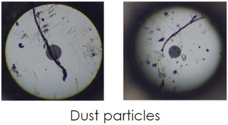
Figure 1: dust particles under the microscope
Sometimes, in fiber optic network, we need to mate two fiber optic connectors together. Will the mating prevent fiber optic connector from contamination? The answer is yes. There is no need to worry about dust with physical contact connectors as long as they were cleaned before the mating process. When the two ferrules are physically mated, the mating force for most single fiber industry standard connectors is around 1kg or about 2.2lbs. If you calculate the force of what 2.2lbs in a 200μm, that comes to 45,000psi which is why contaminate migration is not a problem even in a dusty environment. The following part will provide some answers to some common questions of end users.
Will the Dust Cap Make Fiber Endface Clean?
No, customers should never assume that a capped cable assemblies is clean when taking out of the bag. Dust and mold release agents are the two common contaminates but nearly invisible for the human eyes. The primary purpose of the end cap is to protect the ferrule end face from scratch and pitting defects. It does not protect the ferrule end face from contamination.
If a customer buys a new fiber jumper from the manufacturer and inspects it after taking the end caps off, it would not be uncommon to see some small amount of on contamination on the endface. This does not mean that the jumper manufacturer’s quality process are lacking. All manufacturers experience this. The customer just needs to work smartly and realize that the end cap is just for protecting against scratches. The best practice is to inspect the ferrule, clean if necessary and re-inspect before mating. If the customer does not have a ferrule scope available, then cleaning both connectors end faces before mating will significantly reduce the likelihood of damage and cross contamination.
How to Keep the Fiber Optic Connectors Clean?
Keeping fiber connections clean is different from any other type of cleaning due to the relative sizes of the connectors compared to the particles and contaminants that typically reside on them. Also we need to be diligent in their maintenance by cleaning the connectors every time before they are mated and after each un-mating. Static charges attract dust to the fiber connectors and prevent them from falling off even when blown with a can of compressed air. As we have discussed in the above article, dust caps are primarily used to protect the ferrule and can actually make a clean connector dirty due to their tendency to keep a static charge.
one-click-cleaner
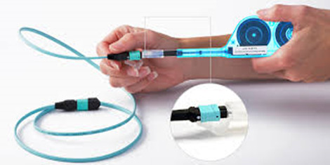
Figure 2: use one-click cleaner to clean the MPO cable
The mechanical cleaning tools like the One-Click cleaners are widely used in the optical fields. . One-click cleaner is designed to clean male connectors, female bulkhead adapters, fiber patch cables and test equipment. It cleans the ferrule endface removing from dust, oil and other contamination without scratching the endface. Although it is the most cost-effective and time-saving solution for cleaning fiber optic connectors, it has a limited contact region and will never be able to clean the connector’s end face. Therefore, another fiber optic cleaner has given to birth—Fiber Optic Cassette Cleaner. The cassette cleaner can wipe away contamination from optical connector endface with ease. I’s very easy to use and suitable for LC/MU/SC/FC/ST/MPO/MTRJ connectors. Usually, the body of this cleaner is made from antistatic materials which will not produce dust.
Is Dry Cleaning a Better Solution?
Besides the mechanical cleaning tools, there are two basic methods :dry cleaning and wet cleaning. There are two distinct advantages a wet cleaning process has over the dry process. The first process is static dissipation and the second is the cleaning solvent’s ability to loosen up harden contaminates from the ferrule end face without causing permanent defects to the end face.
On the other hand, the dry wiping process that an operator would do using a Fiber Optic Cassette Cleaner or One-Click cleaner relies on contact friction to remove contamination. When two materials are rubbed together, there is a transfer of electrons between the two surfaces and the imbalance on the surface creates a charged electric force we call static electricity. The two surfaces, one charged positive and the other negative, will try to pull in surrounding particles to being the charge back into a neutral balance. This attraction pulls in the dust particulates in the air and the wear debris on the connector body and adapter. The introduction of a cleaning solvent during a wet-dry cleaning process introduces static dissipative medium for the charge so that it does not stay on the ferrule surface.
Conclusion
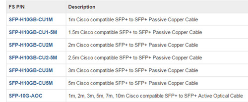
End users should be wise to think of the environment his connectors are being exposed before learn to keep fiber optic connector clean. Because a large enough piece of dust particulate residing somewhere on either ends will create problems. The best practice to avoid long-term problems and extend the life of your optical assemblies is to always inspect and remove any contamination regardless of the connector type. FS.COM offers a full range of fiber optics that can cater to your specific requirement. Bulk Ethernet cable, fiber jumpers, transceivers  and DAC/AOC cables are in great selection. Please feel free to contact us.

Thursday, December 22, 2016

Comparing UTP and STP Copper Cables

Many telecom professionals anticipated that copper cable would eventually be replaced by the fiber optic cable owing to its poor performance in higher-bandwidth application. However, copper cables like cat6/cat6a cable that can support up to 10Gbqs have proven themselves and been widely deployed in the home or office buildings. But for the copper cable, there exists the debate about unshielded twisted pair (UTP) vs. shielded twisted pair (STP). Thus this article aims to provide the detailed information about UTP and STP cables to help users make an informed decision.
Alien Crosstalk (ANEXT)
We all know that copper cable suffer from higher signal loss than fiber optic cable and can be easily interfered by the nearby powers or generator. Alien crossstalk is the performance parameter in copper cables, especially the UTP cables. The following image demonstrates different reactions of the UTP and STP cables to the ANEXT.
utp-anext
So what is the Alien crosstalk? Alien Crosstalk (ANEXT) is a crosstalk that occurs between adjacent cables and connecting hardware. Alien crosstalk in high-speed application is far more severer than in lower-bandwidth infrastructure. It might not be a problem at the lower frequencies of cat 5e and cat 6a cables, but the limiting noise source of the cat 6a systems.
In UTP copper cabling, the alien crosstalk will increase when adjacent cables are close proximity, which is indeed a nightmare to users. Therefore, it is typically recommended to let cat6a cable lay loosely in pathway instead of tight, twisted bundles. People usually have the misconception that if they use STP cables, then alien crosstalk would not be a problem. However, if the shield is not terminated correctly even a shielded system can fall foul of alien crosstalk.
UTP and STP Copper Cable
Twisted pair cables are widely used in transmitting information, especially across great distances. The twist in the wire cancels out any magnetic interference that may develop in the wiring. There are two common types of twisted pair cabling, STP and UTP.

Unshielded Twisted Pair (UTP)

Unshielded twisted pair cable has four pairs of wires inside the jacket. Each pair is twisted with a different number of twists per inch to help eliminate interference from adjacent pairs and other electrical devices. Unshielded twisted-pair cable does not rely on physical shielding to block interference. It relies instead on balancing and filtering techniques using media filters, baluns or both. Noise is induced equally on two conductors and is canceled out at the receiver.
With properly designed, manufactured and installed UTP cable, the network is easier to maintain than one in an STP cable plant, with its shielding continuity and grounding issues. UTP cables can be found in different categories, for instance, cat 5 UTP for specifications to 100 MHz and cat 6a UTP cables for specifications to 500 MHZ. Best buy Ethernet cable you can afford, most small business would purchase Cat 5e or Cat 6 cables.
utp-stp-cable

Shielded Twisted Pair (STP)

Shielded twisted pair cable contains a hidden metal coating that protects wires from radio and electromagnetic interference. How effective the shielding is depends on the material used for the shield, its thickness and frequency, the type of electromagnetic noise field, the distance from the noise source to the shield, any shield discontinuity and the grounding practices. Also, crosstalk and signal noise can increase if the effects of the shield are not compensated for.
When people install and maintain them properly, STP cables greatly reduce crosstalk. This enhances dependability and boosts data transmission speeds in buildings that contain microwave equipment, HVAC systems or radio transmitters. There are many acronyms used on the market to describe shielded cables, from STP to F/FTP; while many are often used synonymously, nearly all of them have different meanings. This blog provides basic information about each style, as defined by ISO/IEC 11801:200, to clear up the confusion.

F/UTP (FTP)

An overall foil shield (F) with unscreened twisted pairs (UTP). This cable is very much like common UTP cables, with the addition of foil underneath the main cable jacket. Another common name for this cable is FTP. F/UTP cables are common in 10GBaseT applications.

S/UTP

An overall braid screen (S) with unscreened twisted pairs (UTP). This is occasionally referred to as an STP cable, but beware: There are other shielded cables among this list that may also claim this term. To be sure, always check to see whether your cable will have any kind of overall barrier, and whether the individual pairs have their own shield.

SF/UTP

Both an overall braid screen (S) and foil shield (F) with unscreened twisted pairs (UTP). This cable is also occasionally referred to as an STP cable. Cables with an overall braided screen are very effective at protecting EMI from entering or exiting the cable, but heavier, thicker and more difficult to install than its UTP counterpart.

S/FTP

An overall braid screen (S) with foil screened twisted pairs (FTP). The ‘shield’ underneath the jacket is a braid, and each individual pair is surrounded by its own foil barrier. The purpose of the additional foil on individual pairs is to limit the amount of crosstalk between them.

F/FTP

An overall foil shield (F) with foil screened twisted pairs (FTP). Similar to F/UTP cables, these shielded cables are commonly used in 10GBaseT applications.

U/FTP

No overall shielding or braid (U) with foil screened twisted pairs (FTP). This type of shielded cable is commonly used in 10GBaseT applications as well.
To sum up
  • STP cables are shielded, while UTP cables are unshielded.
  • STP cables are more immune to interference and noise than UTP cables.
  • STP cables are better at maximizing bandwidth compared to UTP cables.
  • STP cable cost more per meter compared to UTP cables.
  • STP cables are heavier per meter compared to UTP cables.
  • UTP cables are more prevalent in SOHO networks while STP is used in more high-end applications.
Which One Should I Use?
A key factor in this decision is an analysis of how prevalent EMI will be in the installation environment. EMI is commonly caused by nearby motors, generators, air conditioners, and even office mainstays such as fluorescent lights and printers. EMI can cause crosstalk between circuits, resulting in degradation of data, increased errors and slower transmission rates.
While even UTP cables reduce some EMI, shielded STP cables more effectively block interference. STP cables are ideal for high-speed networks such as data centers where 10GBase-T networks are used because 10G Ethernet is significantly more sensitive to EMI. Shielded cables also come in handy when installers must run wires next to fluorescent lights, microwave ovens or powerful motors.
STP cables are also used in outdoor environments where the cables are exposed to the elements and man-made structures and equipment that may introduce additional interference. It also stops criminals from using jammers to interrupt communications between cameras and indoor monitors or recording equipment.
However, people use UTP cables in the vast majority of homes, offices, and even in large scale businesses due to its lower cost. Unshielded phone and network wiring performs well in most buildings. If you don’t have major concerns about interference, it’s wise to avoid the cost and complexity of STP wiring.
Note that shielded cabling is more expensive than unshielded cabling and more difficult to install; it’s stiffer, making it less flexible. The cable also has a larger diameter, taking up more space in conduit. UTP, on the other hand, actually provides faster transmissions in the absence of EMI. It’s less expensive to purchase, easier to install and has been the standard for many years, so it’s already in place in most existing installations.
Conclusion
It is really doesn’t matter whether you use STP or UTP cables, make sure to install high-quality cabling. High-quality cabling will get you out of the trouble, reducing long-term replacement and labor costs. FS.COM offers a full range of UTP and STP copper cables with great customer feedback. If you are still not sure what type of wiring you need, please visit fs.com.

Thursday, December 15, 2016

Eight Factors Influencing Your Fiber Optic Installation Bills

Nowadays more than one third of the popularity have access to the internet. Large enterprises already use the high-capacity fiber-optic access networks, and small- or medium-sized businesses also want to relieve the bottleneck of the copper-based access network and benefit from the fiber-based access network. Nonetheless, costs is one of the factors that small business would take into account. In fact, the cost of large-scale fiber optic deployments depends on a wide range of factors, including redundancy and survivability need, access to the closest fiber line, labor cost, Aerial vs. Underground, and the fiber maintenance cost. The following article concludes several factors that will have great impact on the costs of building a fiber optic network.
office-builing-cabling
Figure 1 shows the layout of the fiber optic network in an office building.
Reminder:
Every building is situated differently, has different surroundings, different neighbors, and different physical dynamics influencing access to fiber lines, how much you’d have to spend on installation will be determined according to the specifics situation. Therefore, the factors listed below can not fit every situation. And we will not present the available materials that are likely to be used in you network as each installation requires its own assessment to determine final fiber optic network.
Redundancy and Survivability Needed
In a network designed with redundancy in mind, each portion of the network is constructed as part of a ring and economical construction is possible. On the other hand, when redundancy is constructed after the fact, it requires a custom cable pathway, usually doubling (or more) the construction cost.
Recently nearly 99 percent of the network will need two redundant physical paths from the network to its location, along with an electronic infrastructure to accommodate failure of a fiber route or an electronic component, and backup power of sufficient duration. And it also need to provide a 24-hour network operations center, a fiber repair crew, intrusion detection, and backup management and recovery facilities.
If network users do not require this level of availability, the network operator should determine their actual current and future requirements, and which subset of survivability and redundancy tools are needed. Ideally, any needs for physical redundancy will be included in the initial project design.
Labor Costs
Although the fiber equipment costs have fallen, skilled labor costs have risen. So how can operators limit those high labor costs and still deploy a quality fiber network that can handle the bandwidth needs of today’s subscribers?
Labor typically forms the majority of the cost of construction—approximately 50 to 80 percent. Therefore the quantity of fiber strands and cables, a materials cost, is typically a secondary consideration. Labor costs are highly variable. For example, poor economic conditions may lead construction companies to reduce their fees, while mobilization of contractors may increase their bid rates if there is suddenly high demand for immediate construction. In general, large-scale ventures have an advantage in managing costs, because construction companies feel comfortable offering lower rates when they expect to profit from the volume and duration of a project.
Ability to Reuse Existing Infrastructure
Reuse the existing infrastructure is not only a cost-saving solution, but an eco-friendly option for overall users. There are a number of options for using existing cable infrastructure. For example, if there is sufficient space in the existing conduit, then you can take advantage of conduit by adding new capacity to your building, which will make your installation substantially simpler and cheaper. Furthermore, whether the existing conduit already lead straight up into your building, or it is configured through twists and turns will have a major impact on the costs of its installation. That’s it, winding paths are trickier than straight cables.
Let’s solve a problem in arithmetic. The cost of a 6-count fiber cable is $2,000 per mile, while an 864-count cable is $50,000 per mile, implying a marginal cost of approximately $50 per fiber per mile. Actual costs for fiber purchase or lease, of course, reflect market costs and depend on the total availability of fiber over the route—and are thus, typically, considerably higher; however, fiber lease or purchase may be a serious consideration over routes where construction is difficult or costly and considerable fiber has already been installed.
Aerial vs. Underground
Typical construction is a mixture of aerial and underground techniques, in part because aerial construction also is more vulnerable to extreme weather, particularly in wooded areas and areas with frequent ice and high winds. And another reason is that aerial construction may be more expensive when poles are crowded or when the utility pole owner charges high rates for access. Worst-case costs can be $100,000 per mile (which usually would lead a network owner to build underground or over another route).
Underground construction also has a wide cost range. In areas where restoration is not important and long continuous runs are possible, “plowing” the fiber into the ground is an inexpensive option—approximately $70,000 per mile. For more detailed information about aerial and underground construction, please see an article entitled “Whether to Go for Aerial or Underground Deployment”.
Based on the estimated percentage of aerial and underground plant we identified in our field survey, we estimate that the difference between aerial and underground construction in Santa Cruz is more than $80,000 per mile, as shown in Table 2.
aerial-and-underground
Table 2: comparison of estimated aerial and underground construction costs.
Cable Management
Of cause, wire management is the most important part of any installation, especially for data communication. For better cable management in server room or the data center, IT racks, fiber enclosures and patch panels should be used. To determine what type of panels you need, take into consideration the space that will be utilized for the network. If you are installing inside of a closet or other cramped quarters and need low density, wall mountable panel is the best choice because it does not take up a lot of room. If racks are already in place, or if there is enough room to install them, rack-mount tray is the best choice because it is sturdy and easy to access. Keep in mind that rack-mount tray does not protect against environmental conditions.
rack-mount-accessories
Figure 3 shows the required equipment for better cable management.
Open frame racks are suggested for this server room, which can provide more flexible cabling environment. The using of fiber enclosure and adapter panels should depend on the fiber count.
The Location of Your Network
The single greatest determining factor not only to how much installation costs, but also how difficult it is to accomplish. Is fiber local or close to your office building? Or do you have to cross a state highway to extend fiber into your site? The nature of the physical terrain that the fiber needs to traverse to reach your building becomes significant. If you have to cross a state highway to bring the nearest fiber to your building, overcoming that obstacle will significantly impact the overall costs. Special use areas such as historical sites can often cause a problem for bringing fiber directly to your building. If there are any of these sites nearby your location, they could potentially impact the costs of fiber installation, depending on the route fiber needs to take to your facility.
And when the fiber is brought to your building, do you have a telecommunications room with the necessary space for installation already available? If so, that will streamline your installation costs, and ensure connectivity continuity once the installation is complete. As you may be gathering, every potential wrinkle in the process of installing fiber has the potential to make it more complicated, and everything that does in fact represent a hurdle has the potential to make the final charges more costly.
Power for Fiber Technology
How easily is sufficient power for fiber accessible from your telecommunications room? If there is ample power available, or if an emergency generator can be used to insure up-time of activated service, then you will save in fees that would require the introduction of additional power capabilities.
Fiber Maintenance Costs
Fiber optic cable is resilient compared to copper cable and coaxial TV cable. The fiber itself does not corrode, and fiber cable installed over 20 years ago is still in good condition. However, fiber can be vulnerable to accidental cuts by other construction, traffic accidents, and severe weather. In other networks of this size, we have seen approximately 80 outages per 1,000 miles of plant per year.
The fiber optic redundancy from the hubs to the FDCs in the backbone network will facilitate restoring network outages while repair of the fiber optic plant is taking place. Depending on the operational and business models, you might be responsible for adds, moves, and changes associated with the network as well as standard plant maintenance. These items may include:
  • Adding and/or changing patching and optical splitter configurations at hubs;
  • Extending optical taps and laterals to new buildings or developments;
  • Extending access to the FTTx network to other service providers;
  • Relocating fiber paths due to changes such as the widening of roadways;
  • Participating in the moving of utilities due to pole replacement projects;
  • Tree trimming along the aerial fiber optic path.
Conclusion
If you are still with us, and concerns about the cost of the installing a fiber optic network, please do not feel hesitate to contact FS.COM for a free consultation. We’ll be happy to provide you with the perfect solutions that meets your specific needs, and clarifies all the above factors that contribute to the bottom line. We offer a full range of enterprise network solutions including the 10G/40G switches, optical transceivers, high-density fiber optic cables, etc.

Wednesday, December 7, 2016

How to Choose the Fiber Optical Solution for Cisco Catalyst 4500-X Series Switch?

We can’t deny the fact that Cisco is one of the most important developers of network devices in the world. They supply a full range of switches including the Nexus, ME, Meraki, Blade, and Catalyst lines. Each of them is designed for unique applications, for example, Catalyst Switches is made for Campus Networks and Nexus Switches for Data Centers. Catalyst 4500-X series switch as one of the intriguing new switch of the catalyst lines, is a cost-effective, fixed aggregation for campus LAN network that brings in 10GbE uplinks. Featured with small size, high scale, this switch is warmly welcomed by overall users. Today’s article will provide some detailed information about this switch, and some advice about how to choose the right optical solutions.
Features of Catalyst 4500-X Series
Catalyst 4500-X switch is available in four versions: 40-port, 32-port, 16-port, and 8-port. Cisco offers seven different chassis of the series, namely Catalyst 4500X-16, Catalyst 4500X-24-IPB, Catalyst 4500X-24-ES, Catalyst 4500X-32, Catalyst 4500X-40, Catalyst 4500X-F-16, Catalyst 4500X-F-32. Remember to pick the right one that meets your needs. Compared with the Catalyst 3850 switch (also known as the 3750-X successor), we can clearly see its advantages, which has been displayed in the below part.
cisco-catalyst-4500-x-3850-fiber-switches
  • Cisco Digital Network Architecture
Only Cisco delivers a digital-ready approach that starts at the edge and extends to where applications reside.
  • Platform scalability
The Cisco 4500 offers up to 800 Gbps of switching capacity. It can scale up to 1.6-Tbps capacity and provides resiliency with Virtual Switching System (VSS). VSS refers to a method that can combine two physical switches into one logical switch to achieve physical redundancy, spanning free blocking elimination and increased bandwidth. That means any two Cisco catalyst 4500-X series switch can be pooled together into a VSS.
vss-on-cisco-4500-x-series-switch
  • High availability
Simplify network deployment and management with easy virtual networks (EVN). The 4500-X also reduces energy costs. Furthermore, device resiliency features such as redundant hot-swappable fans, power supplies, and AC to DC failover and vice versa remove single points of failure in the network.
  • Application monitoring
Get enhanced application monitoring through Flexible NetFlow and 8 ports of line rate bidirectional Switched Port Analyzer (SPAN)/Remote Switched Port Analyzer (RSPAN). Cisco IOS XE Software provides the ability to host third-party applications.
  • Security
Enhance security with support for Cisco TrustSec and Flexible NetFlow technologies.
  • Simplified operations
The 4500-X offers support for Smart Install Director. Customers gain a single point of management for zero-touch deployment of new switches and stacks in campus and branch networks.
How to Choose the Optical Solutions for Catalyst 4500-X?
As noted before, the 4500-X ports support both SFP+ 10GbE optics and 1GbE modules. No matter what type of Catalyst 4500-X series switch you use, you will face the same problem of how to select the right one. The following image shows a 32-port chassis catalyst 4500-X series switch (front view).
catalyst-4500-x-32-port
1—UID LED and switch combination
2—STATUS LED
3—PS1 LED
4—PS2 LED
5—FAN LED
6—USB ports
7—The 16 port version of the chassis does not have the block of 16 ports on the right side of the front panel.
8—Port status LEDs
9—8-port uplink module (Included as part of the WS-C4500X-24ES and WS-C4500X-40ES chassis; available as an optional upgrade on the other Catalyst 4500-X series chassis)
As noted before, each Ethernet port requires either an SFP or SFP+ transceiver be installed to operate. The common used pluggable modules includes the three types—copper cable with RJ45 connector, direct attached cable and the pluggable transceiver module with the fiber patch cable. Before making the move, it is necessary for us to review the basic knowledge of the fiber optic transceiver (SFP and SFP+), DAC cables and fiber patch cable that are available for Catalyst 4500-X switch.
Cisco SFP and SFP+ Optical Transceivers
Fiber optic transceiver is a device that comprises of both a transmitter and receiver of analog or digital signals. It is usually inserted into optical devices like switch, router or network interface cards which provide one or more transceiver module slot. Cisco SFP modules and SFP+ optical transceivers are available in different standard. The following table has listed some of them, which you might want to have a look at it.
cisco-compatible-sfp
Figure 4 shows available Cisco SFPs for Catalyst 4500-X Series Switch
cisco-compatible-sfp
Figure 5 shows available Cisco SFP+ for Catalyst 4500-X Series Switch
Fiber Optic Patch Cables
Fiber Patch Cable, also known as fiber jumper or fiber optic patch cord is designed to interconnect or cross connect fiber networks within structured cabling systems. According to fiber cable mode, cable structure or connector types etc., fiber patch cable can be divided into different types. But remember that your fiber patch cables should always be compliant with the existing optical transceivers. For instance, LC LC multimode patch cord can be only used on the multimode optical transceivers (1000BASE-SR SFP or 10GBASE-SR SFP+). If you know nothing about this, it is advisable for you to talk with your supplier.
SFP+ Cables
SFP+ cables is the cost-effective solution for users in telecom field. It usually comes in DAC and AOC cable types. This fiber optical solution is suitable for short link applications within racks and across adjacent racks. Compared with the optical transceivers based system, it is inexpensive and more convenient. The available SFP+ cables are listed in the below chart.
10g-sfp-dac-cables
Fiberstore Fiber Optic Transceivers & Fiber Patch Cable Solutions
To sum up, in order to find the perfect fiber optic solution for your network, firstly you need to understand your needs, and consult with your vendors, then purchase all the available equipment within the budget. All the above optical devices like the copper cable, fiber optic cables, SFP & SFP+, and SFP+ DAC cables are provided at Fiberstore. You don’t need to worry about the compatibility issue because all of our products are tested in our test center before shipping. Furthermore, they are even backed by a lifetime warranty. Custom service is also available to fit your specific requirement.

Monday, December 5, 2016

Do You Know How Fast Your Fiber Optic Internet Can Be?

It is no secret that the technology is continually evolving, so does the demand for consistent and accessible information and entertainment. From the old 56 kbqs crawl of dial-up, to the early 1 Mbqs copper connections and all the way to the existing popular 1 Gbqs, 10 Gbqs/40 Gbqs fiber optic connections, we’ve gone through a drastic improvement to maintain a stronger signal, a better connection, a faster speed. It seems that the intricacies of internet can get complicated, so how do you draw the line with your internet consumption and speed demands? So in this blog post, we explain how fiber optic works, why cause the boom in fiber optic speed and how fast fiber optic internet can be.
How Does an Fiber Glass Function in the Internet?
We know that fiber optic cable works like a bridge between the consumer and internet supplier. But how does this process actually work? To put it simply, fiber cable works by sending data as pulses of light through a glass fiber. At one end of the fiber, a laser or LED transmits data as light. At the other end of the cable, the light will be interpreted into data by the light-sensitive receptors.
If the above explanation is not clear to you, then here comes the more vivid description. Fiber optic cables consists of a strand of fiber glass wrapped in a protective jacket called cladding. Owing to the total internal reflection, light can go from one end of the core to the other end without ever changing its wavelength. More detailed information, please see an article entitled “A Quick Lesson In Fiber Optics”.
Fiber Optic Cable Types: Single-mode and Multimode Fiber
Single-mode and multimode fibers are the two broad categories of fiber core that can affect how light can travel through the cable. In single-mode fiber optic system, there is only one pathway or mode that light can travel along. While in multimode fiber optic system, seen in the below image, there are multiple pathways just like a circus funhouse with beams of light traveling along a variety of pathways through the core.
single-mode-and-multimode-fiber
Theoretical, if you have one light beam traveling in both the single-mode and multimode fibers, the straight line beam of the single-mode fibers will reach its destination first. This difference is usually caused by the modal dispersion, which explain the reason why we often use the single-mode fibers for longer reach application.
WDM and Dark Fibers
The advent of WDM (wavelength division multiplexing) in the mod-2000s as a great breakthrough in fiber optics as it allows multiple channels to be carried at the same tine on a single fiber optic cable. There are all together CWDM and DWDM systems, CWDM or course WDM is the initial implement that allows 4 and 8 wavelengths, such as the Ethernet LX-4 standard which allowed a cable to carry four 3.125 Gbit/s data channels, resulting in 10Gbit/s aggregate.
In DWDM (Dense WDM) system, even though it is much more expensive, it can handle up to 160 data channels expanding basic a 10 Gbit/s system over a single fiber pair to over 1.6 Tbit/s.
dwdm
Figure 2 display different wavelengths can be bundled together in the same mode.
In terms of the new concept—dark fiber, it represents the unused cable laid in the network as space capacity, carrying high amounts of data at high speeds over hundreds of miles. Simply put, with DWDM, dark fiber network can easily increase bandwidth and allow more data to be send via optical fibers. And as the price reduces, dark fibers are gradually becoming more popular than ever.
How Do You Find out What Speed You Need?
This seems to be a noob question. As you can simply use the speed testing websites to discover the speed of your internet connection. And tracking the aspects of your internet use can give a better ideal of what speed you have and the speed that is optimal for you. What I want to express here is the common mistakes you will make.
It is not always the ISP’s fault, if your speeds are slower than what you expect. Several factors might have great impact on the accuracy of speeds. For example, the types of the hardware you have, the age/types of the line you have, and how busy the internet is at all time.
To find what speed you need depends on several different elements. How you plan to use the Internet, how many devices you have in your home, and how fast you expect to be connected are just a few factors that influence which speed is right for you. For office network, network speed under gigabit Ethernet is not sufficient.
Remember, speed is a maximum level, not a guaranteed one. As your desire for a faster connection increases, be sure you have the Internet speed that will exceed your technological needs!
The Next Steps for Fiber Optics
The modern commercial fiber optic system enjoys it stay in the Gigabit Ethernet speed. But we can look forward to the increases in the range of gigabits per second down speed, perhaps even breaking into the terabit range, in the not so distant future.