Wednesday, March 30, 2016

The Reality of Copper and Fiber Cable

The war between copper and fiber has been raged for years and it is never ended. Copper-based systems maintain the same upgrade path that they have for years, while fiber-optic proponents continue to advocate their sense of superiority, which forces people to face the dilemma of selecting copper or optical fiber. So, once again, which cabling type is the best overall value for their current and projected future needs? This article carefully looks into the question and gives you the reality of the present copper and fiber cables.

Major Difference Between Copper and Optical Fiber
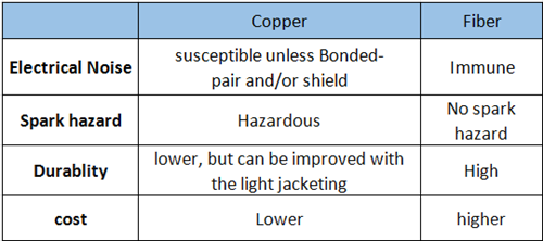
Cable length and data rates are two of the key criteria that differentiate the use of copper or fiber optic cable. If you require a long link length and high data rate, then fiber cable may be the obvious choice, and you can move on to selecting a specific fiber cable. Alternatively, if the runs are short and the data volume fits within copper's capacity, then copper it is. Some other general differences between copper and fiber optic cables are offered in the table. Once you understand the distinct properties of copper and fiber, your solution may seem clearer. Now let’s come to the reality of both cables to help you select the suitable one.

difference between copper and fiber cable

Copper Cabling in Gigabit Ethernet Application
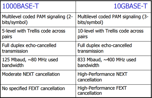
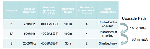
Category 6 or Cat6 data cabling as one of the most popular copper cables in the market today, has been utilized for Gigabit Ethernet and several other network protocols. As the sixth generation Ethernet cables formed from twisted pairs of copper wiring, cat6 is composed of four pairs of wires, similar to cat5 cables. The primary difference between the two, though, is that cat6 makes full use of all four pairs. This is why cat6 can support communications at more than twice the speed of cat5e, allowing for Gigabit Ethernet speeds of up to 1 gigabit per second.

copper cabling

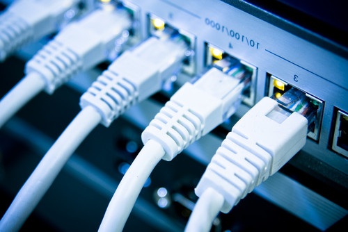
However, there are some link restrictions in using this type of data cabling. When used for 10/100/1000BASE-T, the restriction of the copper cable is 100 meters, and when used for 10GBASE-T, the restriction is 55 meters. Another issue is that there are some cat6 cables that are very large and are quite difficult to connect to 8P8C connectors (a type of modular connector used for communications purposes such as phone/Ethernet jacks) when the user does not have a unique modular piece.
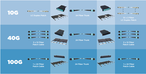
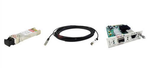
Copper cable still has a place in the telecom field, the best prove is that copper cable has improved itself to face the ever-increasing bandwidth requirement. For 40G Ethernet, there are 40G DAC cables — passive copper cable or active copper cable available in the market to achieve 40G connectivity. For example, Cisco QSFP to QSFP+ copper cables, like QSFP-H40G-CU1M and QSFP-H40G-ACU7M are widely used to connect within racks and across adjacent racks.

Fiber Optic Cabling
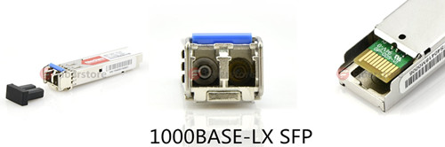
Fiber optic cable is completely unique from cat6 and other types of copper cabling systems. The most obvious feature about optical fiber is that it draws on light instead of electricity to transmit signals. In addition, optical fiber is immune to electrical interference, which means that a user can run it just about anywhere, anytime. However, fiber is not that easy to install. Terminating fiber optic cable is not as simple as copper. While manufacturers have developed crimp-on connectors, they are expensive, high loss and have not been very reliable. Fiber optic connectors need adhesives for reliability and low cost. And most installation involves stripping fibers, injecting adhesives and polishing the ends. No IDC (insulation displacement connectors) here. Any good installer can learn how to terminate fiber in less than 2 hours. The following picture shows a singlemode and multiomde optic cable.

singlemode and multimode optic cable

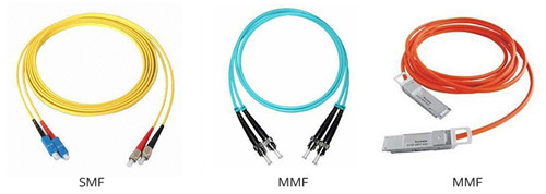
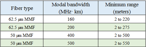
Not all fibers have infinite bandwidth. At least not the multimode fiber used in most premises networks. It's a lot higher than copper, but as you approach gigabit speeds, you are limiting the distances available for links to 500 meters or so. Singlemode fiber, as used in telecom and CATV networks, practically has infinite bandwidth. But it uses higher cost components and can be pricey for shorter links. It's not necessary for today's networks but may be for the next generation. Well, fiber prices continue to fall while copper prices rise.

Know Your Application, Then Select Your Cable
Just as knowing it’s vital to select the right switches, routers and firewalls for an industrial Ethernet network, it is also vital to select the right cable. When it comes to industrial Ethernet cable, long reach and high data volumes call for fiber cable. For short runs and average data requirements, copper cable will do the job. Next consider the operating environment and mechanical devices will face to help you on a final choice. Fiberstore provides various copper cables and fiber cables, including OM3 cable, OM4 cable, Cat6A copper cable, Cat5A copper cable and other specific cables. 40G DACs and AOCs are also offered. You won;t miss it.

Monday, March 28, 2016

Some Basics About Migration to 40G Ethernet

Fiber optic links are vital for providing the bandwidth and speed needed to transmit huge amounts of data to and from a large number of sources. Recently more bandwidth is greatly needed to support the use of virtualization and improved space utilization in the data center. 2010 witnessed the ratification of 40 and 100 gigabit Ethernet (GbE) standard, since then leading switch manufacturers offered 40 GbE blades and more than 25% of data centers have implemented these next generation speeds. It is anticipated that by the end of this year, more and more data centers will follow suit. Therefore today’s article will provide an effective solution to help you migrate from current data center applications to 40/100 GbE.

10G OM3/OM4 Connectivity in the Data Center
The IEEE 802.3ae 10G standard released in 2002 included 10GBASE-SR OM3 guidance that can operate at 850nm with duplex fiber serial transmission. Even though duplex fiber implied duplex LC connectivity throughout the channel, 12F MPO terminated cables emerged as a primary choice for deployment in data-center backbone applications. The 12F MPO terminated trunk cable provided the highest fiber packing density to maximize pathway and space utilization in ducts, raceways, and patch panels. For example, 46C3447 is IBM BNT 10GBASE-SR SFP+ that operates over OM3 cable for a distance of 300m with LC duplex connector. An MPO connectorized backbone cable typically is terminated in patch panels using one of two methods that break-out the 12F MPO to six 2F duplex LC (Figure 1).

10G connectivity
Standards From 10GbE to 40/100GbE
Similar to how transportation highways are scaled to support increased traffic with multiple lanes at the same speed, the 40 and 100 GbE standards use parallel optics, or multiple lanes of fiber transmitting at the same speed. Running 40 GbE requires 8 fibers, with 4 fibers each transmitting at 10 Gbps and 4 fibers each receiving at 10 Gbps. Running 100 GbE requires a total of 20 fibers, with 10 transmitting at 10 Gbps and 10 receiving at 10 Gbps. Both scenarios call for using high-density multi-fiber MPO style connectors.

40G connectivity
According to IEEE 802.3ba standard, multimode optical fiber supports both 40 and 100 GbE over link lengths up to 150 meters when using OM4 optical fiber and up to 100 meters when using OM3 optical fiber. It is important to note that single-mode fiber can also be used for running 40 and 100 GbE to much greater distances using wavelength division multiplexing (WDM) for most data center applications of less than 150 meters. Copper twinax cable is also capable of supporting 40 and 100 GbE but only to distances of 7 meters. Take EX-SFP-10GE-DAC-1M as an example, it is Juniper SFP+ passive copper cable, which is ideal for 10G interconnect application for a link length of 1m.

Migration From Duplex Fiber Transmission to 40/100G Parallel Optics
Based on a MPO system, migration from 10G to 40G to 100G seems to be a simple and easy deployment. Starting with a 10G configuration, a base 12F MPO backbone cable is deployed between the 10G switches. As discussed earlier, modules or harnesses are used at the end to transition from the 12F MPO to LC duplex. These breakout configurations enable connectivity into the switch.

transition to 40G
And when the switches migrate to 40G, the 10G module or harness is removed and should be replaced by a conversion module or conversion harness as shown in Figure 3 and Figure 4. Alternatively, an MPO adapter panel can be used. In any of these deployment options, the use of an MPO terminated jumper is needed to establish connectivity between the switches. For 100GBASE-SR4 networks all Figures 4-6 cabling is applicable.

Conclusion
To keep up with the path of future, MPO-based connectivity using OM3 and OM4 is the ideal solution for the data center, which makes the transition to 40/100G more easier and efficient. Fiberstore offers various types of 40GbE transceivers, MPO/MTP trunk cable, MPO/MTP harness cable, MPO/MTP cassette and other assemblies for your 40G network connectivity. For more information about our products, please contact us directly.

Thursday, March 24, 2016

Choose 12-fiber or 24-fiber for 40/100G Migration

There is no doubt that 40 and 100 GbE are just around the corner, or the reality is coming. To keep up with the pace, data center managers are striving to determine which fiber optic links will support 10 GbE today while future proofing the best, most effective migration path to 40 and 100 GbE. Many network designers recommend that the use of 12-fiber multimode trunk cables can provide the best migration path to 40 and 100 GbE. While others confirm that 24-fiber trunk cables with 24-fiber MPOs on both ends is a better standards-based transition path. So which one is the most suitable solution? It all comes down to a brief comparison of these two cables over investment and reduced future operating and capital expense.
24-fiber Solution
The use of 24-fiber trunk cables between switch panels and equipment is a common-sense approach, but people may not be familiar with this optic scenario. In fact, a 24-fiber trunk cable is used to connect from the back of the switch panel to the equipment distribution area. For 10 GbE applications, each of the 24 fibers can be used to transmit 10 Gbps, for a total of 12 links. For 40 GbE applications, which requires 8 fibers (4 transmitting and 4 receiving), a 24-fiber trunk cable provides a total of three 40 GbE links. For 100 GbE, which requires 20 fibers (10 transmitting and 10 receiving), a 24-fiber trunk cable provides a single 100 GbE link as shown in Figure 1.
12-fibers
Maximum Fiber Utilization
As noted before, 40 GbE uses eight fibers of a 12-fiber MPO connector, leaving four fibers unused. When using a 12-fiber trunk cable, three 40 GbE links using three separate 12-fiber trunk cables would result in a total of 12 unused fibers, or four fibers unused for each trunk. But with the use of 24-fiber trunk cables, data center managers actually get to use all the fiber and leverage their complete investment. Running three 40 GbE links over a single 24-fiber trunk cable uses all 24 fibers of the trunk cable. Obviously, 24-fiber is more appropriate for 40/100G migration.
Increased Fiber Density
Because 24-fiber MPO connectors offer a small footprint, they can ultimately provide increased density in fiber panels at the switch location. With today’s large core switches occupying upwards of 1/3 of an entire rack, density in fiber switch panels is critical. Hydra cables feature a single 24-fiber MPO connector on one end and either 12 duplex LC connectors on the other end for 10 GbE applications, 12-fiber MPO connectors for 40 GbE or a 24-fiber MPO connector for 100 GbE. With a single 1RU fiber panel able to provide a total of 32 MPO adaptors, the density for 10 GbE applications is 384 ports in a 1RU (duplex LC connectors) and 96 40 GbE ports in a 1 RU (12-fiber MPOs). Figure 2 shows a 12-fiber MTP trunk cable with MTP/APC connector on both ends largely improves the performance for 40G/100G fiber links.
mtp-jumper-cable
Reduced Cable Congestion
Cable congestion is one of the biggest problems in the data center because it will make cable management more difficult and impede proper airflow needed to maintain efficient cooling and subsequent energy efficiency. In fact, a 24-fiber trunk cable are only appreciably larger than 12-fiber trunk cables in diameter. That means the 24-fiber trunk cables provide twice the amount of fiber in less than 21% more space. For a 40 GbE application, it takes three 12-fiber trunk cables to provide the same number of links as a single 24-fiber trunk cable—or about 1-1/2 times more pathway space.
Cost-effective Migration Path
As 24-fiber trunk cables can effectively support all three applications shown in Figure 3, there is no need to recable the pathways from the back of the switch panel to the equipment distribution area. That means that data center managers can easily migrate to higher speeds with all of that cabling remains permanent and untouched. With 24-fiber trunk cables offer guaranteed performance for 10, 40 and 100 GbE, upgrading the cabling infrastructure is as simple as upgrading the hydra cables or cassettes and patch cords to the equipment.
migration path from 10G to 40&100G
Conclusion
With guaranteed support for all three applications, the ability to use all the fiber deployed, reduced cable congestion and higher port density in fiber panels, and an easy migration scheme, 24-fiber trunk cables offers lower future capital and operating expense. Fiberstore supplies 12, 24, 48, 72, 96 and 144 fiber core constructions with OM1, OM2, OM3 or OM4 fiber trunk cable, these trunk cable assemblies are composed of high quality LSZH jacketed fiber optic cables, connecting equipment in racks to MTP/MPO backbone cables. 40G QSFP+ optical transceivers like FTL410QE2C and QSFP-40G-LR4-S are also provided. If you are interested in any of our products, please contact us directly.

Tuesday, March 22, 2016

Dig Deeper Into SFP Transceivers

Small form-factor pluggable (SFP) is a prevailing type of optical transceivers in the market widely utilized for Gigabit Ethernet application. As it has the same function with GBIC but with a smaller size, SFP transceiver is also called mini-GBIC. Optical transceivers are typically designed to both transmit and receive electrical optical signals under the Multi-Source Agreement. Each SFP module can support data rates from 1Gbps to 10Gbps. And there are a number of SFP modules and network accessories available for you to select from. Which one suits you better? The following article will dig deeper into the SFP transceivers that will help decide which one will work best for you.

SFP transceivers have a variety of different transmission and receiving type, users can select the appropriate transceiver for each link, to provide the optical performance can be achieved based on the available fiber type (such as a multimode fiber or single-mode fiber). Optical SFP modules available are generally divided into the following categories. Figure 1 displays the basic components of a SFP transceiver.

SFP transceiver 

1000BASE-LX—Specified in IEEE 802.3 Clause 38, 1000BASE-LX uses a long wavelength laser (1270-1355 nm), and a maximum RMS spectral width of 4nm. 1000BASE-LX is designed to cover a distance of up to 10 km over 10µm single-mode fiber. 1000BASE-LX can also run over all common types of multimode fiber with a maximum segment length of 550 m. For link distances greater than 300 m, the use of a special launch conditioning patch cord may be required. E1MG-LX-OM is Brocade 1000BASE-LX SFP that can work over a distance of 10km.

1000BASE-EX—1000BASE-EX is not a standard but industry accepted term for Gigabit Ethernet transmission. It is very similar to 1000BASE-LX10 but achieves longer distances up to 40 km over a pair of single-mode fibers due to higher quality optics than a LX10, running on 1310nm wavelength lasers. It is sometimes referred to as LH (Long Haul).

1000BASE-ZX—1000BASE-ZX is also a non-standard but multi-vendor term using 1,550nm wavelength to achieve distances of at least 70 kilometers over single-mode fiber. Some vendors can specify distances up to 120 kilometers over single-mode fiber. Ranges beyond 80 km are highly dependent upon the path loss of the fiber in use, specifically the attenuation figure in dB per km, the number and quality of connectors/patch panels and splices located between transceivers.

1000BASE-SX—1000BASE-SX is a Gigabit Ethernet standard for operation over multimode fiber using a 770 to 860 nm, near infrared (NIR) light wavelength for a maximum of 550m at 1.25 Gbit/s (gigabit Ethernet) or 150m at 4.25 Gbit/s (Fibre Channel). Take EX-SFP-1GE-SX as an example, it is 1000BASE-SX SFP that can support a link length of 550m over OM2 cable. Figure 2 shows that EX-SFP-1GE-SX inserts into a Juniper SRX210.

EX-SFP-1GE-SX 

1000BASE-BX10—1000BASE-BX10 is capable of up to 10 km over a single strand of single-mode fiber, with a different wavelength going in each direction. The terminals on each side of the fiber are not equal, as the one transmitting downstream uses the 1490nm wavelength, and the one transmitting upstream uses the 1310nm wavelength.

1000BASE-T—It is a standard for Gigabit Ethernet copper cabling. The maximum length of 1000GBASE-T is 100 meters. 1000BASE-T must use Category 5 cable or better (including Cat 5e and Cat 6. 1000BASE-T can be used in data centers for server switching, for uplinks from desktop computer switches, or directly to the desktop for broadband applications.

1000BASE-TX—Created by the Telecommunications Industry Association (TIA), 1000BASE-TX (TIA/EIA-854) is a standard similar to 1000BASE-T that was simpler to implement. Compared with 1000BASE-T, this simplified design would have reduced the cost of the required electronics by only using two unidirectional pairs in each direction instead of 4 bidirectional. However, this solution has not been widely used largely due to the required Category 6 cabling and the rapidly falling cost of 1000BASE-T products.

Recommended Information It is known that there is no visual difference between the bare SFP modules, so how to differ them? Smart manufacturers figure a way out by marking the color of pull ring to distinguish generally. For example: black pull ring is multimode, the wavelength is 850 nm; blue is the 1310nm module; yellow is the 1550nm module; purple is the 1490nm module and so on. If you are confused with the specifications of the SFP modules, you should find a reliable vendor to help you. Fiberstore provides a variety of SFP modules including 100BASE SFP, 1000BASE SFP, BiDi SFP, CWDM/DWDM SFP, SONET/SDH SFP and 2G/4G FC SFP. Our SFP modules are fully compatible with major brand. For more information about SFP transceivers, please feel free to contact us.

Wednesday, March 16, 2016

Upcoming 40/100G Technology

The past decades witnessed the tremendous advancement in Ethernet network transmission speeds from 10/100 base systems to 1G then 10G deployments. Today, 10G server uplinks are ubiquitous in the data center, driven by the need for higher bandwidth, 40/100G server uplinks are just around the corner. IEEE ratified 40/100G Ethernet Standard in June 2010. Since then people were hoping to embracing this new Gigabit Ethernet. However, migrating to higher data rates seems not be that easy. This article will pay special attention to those aspects that influence the migration path.
New Transceiver Interface: MPO Connector
When transition to 40/100G, parallel optics are needed to transmit and receive signals. Because for 40G, there are 4-Tx and 4-Rx fibers, each transmitting at 10G for an aggregate signal of 40G. And for 100G, there are 10-Tx and 10-Rx. As parallel optics technology requires data transmission across multiple fibers simultaneously, a multifiber (or array) connector is required. Defined by TIA-604- 5-C, Fiber Optic Connector Intermateability Standard, MPO (FOCIS-5) is an array connector that can support up to 72 optical fiber connections in a single connection and ferrule. Factory-terminated MPO solutions allow connectivity to be achieved through a simple plug and play system. And this MPO-terminated backbone/horizontal cabling is simply installed into preterminated modules, panels, or Harnesses.
40G Ethernet Solution
According to IEEE 802.3ba, 40G was designated to support high-performance computing clusters, blade servers, SANs and network-attached storage. When deploying 40G network, QSFP transceiver and a 12-fiber MPO will be utilized. Deployment of 40G over multimode fiber will be achieved with 4-Tx and 4-Rx fibers from the 12-fiber MPO. The fibers will be the outer fibers as shown in Figure 3. Each of these four “channels” will transmit 10G for the combined 40G transmission. While single-mode fiber transmission will remain duplex connectivity using course wavelength division multiplexing. Some transmission media for 40G are to be included in the following table.
40G
  • 40 GBASE-SR4 (parallel optics)
—100m on OM3/125m on OM4, 10G on four fibers per direction
  • 40 GBASE-LR4 course wavelength division multiplexing (cWDM)
—10km on single-mode fiber, 4x 10G 1300 nm wavelength region like QSFP-40GE-LR4
  • 40 GBASE-CR4
—7 m over copper, 4 x 10G (twinax copper)
100G Ethernet Solution
40G is to support increasing bandwidth demand for server computing, while 100G was designated to support switching, routing and aggregation in the core network. For 100G deployments, the CXP will be the electronics interface for OM3/OM4 multimode fiber, while CFP will be the interface for single-mode fiber. For 100G transmission over multimode fiber, the optical connector interface will be the 24-fiber MPO connector that will support 10-Tx and 10-Rx channels, each transmitting at 10G. Transmission over single-mode will be achieved via wavelength division multiplexing with duplex connectivity.
100G
  • 100 GBASE-SR10 (parallel optics)
—100m on OM3 or 125m on OM4, 10G on 10 fibers per direction
  • 100 GBASE-LR4 (dWDM)
—10km on single-mode, 4 x 25G 1300 nm
  • 100 GBASE-ER4 (dWDM)
—40km on single-mode, 4 x 25G 1300 nm
  • 100 GBASE-CR10
—7 m over copper, 10 x 10G (twinax copper)
Cabling Migration From 10G to 40G to 100G in an MPO-based System
Starting with 10G, a 12-fiber MPO cable is deployed between the two 10G switches. Modules are used at the end to transition from the 12-fiber MPO to LC duplex. This enables connectivity into the switch (Figure 3).
10G over 12-Fiber MPO Cabling
For 12-fiber MPO cassette-based optical systems already installed, 40G migration is as simple as replacing the existing cassette from the patch panel housings at the equipment and cross connects with an MPO adapter panel. The use of a 12-fiber MPO jumper is needed to establish connectivity between the switches (Figure 4).
40G over 12-Fiber MPO Cabling
Future 100G networks will require a 24-fiber MPO jumper to establish a link. Systems that use 12-fiber MPO backbone cabling will need a 24-fiber to two 12-fiber MPO jumpers (Figure 5).
100G over 12-Fiber MPO Cabling
Future Proofing
As we transition to 40G and 100G, an MPO-based trunk with appropriate fiber can be installed, which will provide an easy migration path to future higher-speed technology. This article has mentioned some optical devices and cabling solutions to support 40/100G Ethernet. Fiberstore provides a large amount of 40/100G equipment like 40G QSFP+ (JG661A), 40G DAC and AOC, etc. CFP, CFP2, CFP4 and QSFP28 are also offered with very competitive prices and high quality. To best meet the needs of the future, future proofing is crucial. So if you have any requirement of our products, please send your inquiry to us.

Monday, March 14, 2016

The Basics of 1000BASE-SX and 1000BASE-LX SFP

Gigabit Ethernet has been regarded as a huge breakthrough of telecom industry by offering speeds of up to 100Mbps. Gigabit Ethernet is a standard for transmitting Ethernet frames at a rate of a gigabit per second. There are five physical layer standards for Gigabit Ethernet using optical fiber (1000BASE-X), twisted pair cable (1000BASE-T), or shielded balanced copper cable (1000BASE-CX). 1000BASE-LX and 1000BASE-SX SFP are two common types of optical transceiver modules in the market. Today’s topic will be a brief introduction to 1000BASE-LX and 1000BASE-SX SFP transceivers.
1000BASE in these terms refers to a Gigabit Ethernet connection that uses the unfiltered cable for transmission. “X” means 4B/5B block coding for Fast Ethernet or 8B/10B block coding for Gigabit Ethernet. “L” means long-range single- or multi-mode optical cable (100 m to 10 km). “S” means short-range multi-mode optical cable (less than 100 m).
1000BASE-SX
1000BASE-SX is a fiber optic Gigabit Ethernet standard for operation over multi-mode fiber using a 770 to 860 nanometer, near infrared (NIR) light wavelength. The standard specifies a distance capability between 220 meters and 550 meters. In practice, with good quality fiber, optics, and terminations, 1000BASE-SX will usually work over significantly longer distances. This standard is highly popular for intra-building links in large office buildings, co-location facilities and carrier neutral internet exchanges. 1000BASE-SX SFP works at 850nm wavelength and used only for the purposed of the multimode optical fiber with an LC connector. 1000BASE-SX SFP traditional 50 microns of multimode optical fiber link is 550 meters high and 62.5 micron fiber distributed data interface (FDDI) multimode optical fiber is up to 220 meters. Take EX-SFP-1GE-SX as an example, its maximum distance is 550m with DOM support. The 1000Base-SX standard supports the multimode fiber distances shown in table 1.

1000Base-SX standard

1000BASE-LX
Specified in IEEE 802.3 Clause 38, 1000BASE-LX is a type of standard for implementing Gigabit Ethernet networks. The "LX" in 1000BASE-LX stands for long wavelength, indicating that this version of Gigabit Ethernet is intended for use with long-wavelength transmissions (1270–1355 nm) over long cable runs of fiber optic cabling. 1000BASE-LX can run over both single mode fiber and multimode fiber with a distance of up to 5 km and 550 m, respectively. For link distances greater than 300 m, the use of a special launch conditioning patch cord may be required. 1000BASE-LX is intended mainly for connecting high-speed hubs, Ethernet switches, and routers together in different wiring closets or buildings using long cabling runs, and developed to support longer-length multimode building fiber backbones and single-mode campus backbones. E1MG-LX-OM is Brocade 1000BASE-LX SFP that operates over a wavelength of 1310nm for 10 km.

1000BASE-LX-SFP

Difference Between LX, LH and LX/LH
Many vendors use both LH and LX/LH for certain SFP modules, this SFP type is similar with the other SFPs in basic working principle and size. However, LH and LX/LH aren’t a Gigabit Ethernet standard and are compatible with 1000BASE-LX standard. 1000BASE-LH SFP operates a distance up to 70km over single-mode fiber. For example, Cisco MGBLH1 1000BASE-LH SFP covers a link length of 40km that make itself perfect for long-reach application. 1000BASE-LX/LH SFP can operate on standard single-mode fiber-optic link spans of up to 10 km and up to 550 m on any multimode fibers. In addition, when used over legacy multimode fiber type, the transmitter should be coupled through a mode conditioning patch cable.
Conclusion
1000BASE SFP transceiver is the most commonly used component for Gigabit Ethernet application. With so many types available in the market, careful notice should be given to the range of differences, both in distance and price of multimode and single-mode fiber optics. Fiberstore offers a large amount of in-stock 1000BASE SFP transceivers which are compatible for Cisco, Juniper, Dell, Finisar, Brocade, or Netgear in various options. If you have any requirement of our products, please send your request to us.

Wednesday, March 9, 2016

The Evolution Path of BASE-T

With the requirements laid on data center increasing rapidly, the ability to flexibly adapt to future demands is tremendously crucial for data center managers. Often this can be achieved by deploying higher bandwidth solutions in a part of the data center, provided that these systems are backwards compatible with existing infrastructure or it may be a cost-consuming method. BASE-T technology featured by its low cost, availability and flexibility is largely favored by data center designers. This article illustrates the migration of BASE-T technology so that people can future proof their data center tomorrow.
Why BASE-T Is so Popular?
To be short, three main advantages will be concluded in the following part.
1. Least cost access layer alternative when compared to other interconnect technologies
  • Optical (e.g. SR, LR)
  • Direct-Attached
2.Structured topology
  • Common physical interface (RJ45)
  • Flexibility and longevity
  • Optimized for small to medium-sized data centers (< 20K square feet)
3. Supports auto-negotiation and Power-Over-Ethernet
  • Simple plug and play installation
  • Ubiquitous RJ45 interface simplifies 10GBASE-T to 40GBASE-T upgrade path
1000BASE-T—Gigabit Ethernet Over 4-pair Cat 5 Cabling
1000BASE-T (ratified in 1999) is a Gigabit Ethernet standard over copper wiring at the speed of 1000 Mbps. Each 1000BASE-T network segment can support a maximum length of 100 meters, and uses Category 5 cable or better (including Cat 5e and Cat 6). 1000BASE-T also uses a symbol rate of 125 Mbaud and all four pairs for the link and a more sophisticated five-level coding scheme. The 1000BASE-T SFP operates on standard Category 5 unshielded twisted-pair copper cabling of link lengths up to 100 m.
Realizing 10BASE-T
Upgraded from 1000BASE-T, 10GBASE-T (certificated in 2006) offers the most flexibility, the lowest cost media, and is backward-compatible with existing 1 GbE networks. 10GBASE-T connected with Cat 6 and Cat 6A (or above) cabling supports a length up to 100 meters that gives IT managers a far greater level of flexibility in connecting devices in the data center. 10GBASE-T and Category 6A cabling costs less than using either optical fiber or SFP+ direct attach copper (DAC) options that have been widely deployed to date center for 10 Gb/s. For example, EX-SFP-10GE-DAC-1M can only support a link length of 1m that largely limits its application. Figure 1 presents a comparison between 1000GBASE-T and 10GBASE-T.
comparison between two BASE-T technology
Road to 40GBASE-T in Data Center Networks
If there is a 10GBASE-T for switch-to-server and switch-to-switch connectivity, there will be a 40GBASE-T over twisted pair cabling for the 40G data center deployment according to the IEEE. Twisted pair cabling with the RJ-45 connector has always been the first choice for IT professionals, based on its low cost and ease of use. Unlike fiber or twinax solutions, twisted pair cabling can automatically switch to different data rates, such as from 100MbE to 10GbE. Therefore migration to 40GBASE-T does not require a upgrade of all the equipment of the data center, which will reduce of the overall expenditure of the data center.
The advantages of 40GBASE-T are clear, but the path from initial ratification to commercial availability is not always smooth. There still a few months off for 40GBASE-T standardization, here comes some good news, as well as some considerations.
40GBASE-T is specified with transmission performance up to 2 GHz (four times the bandwidth of Category 6A) with a lot more stringent alien crosstalk requirements. Since initial 40GBASE-T applications would be limited to data centers, the traditional twisted pair Ethernet 100m link length is not essential. Additionally, Industry players helping in the development of an industry standard for 40GBASE-T have to ensure that it could be supported and rolled out cost-effectively. The new standard will minimize the time it will take to develop new electronics for switches and servers that can support 40GBASE-T connectivity, by building on the work already completed to support 10GbE connections. The standard will also support the ubiquitous RJ-45 connector. Sooner or later, 40GBASE-T will be upon us. Nowadays 40GBASE-LR4, 40GBASE-SR and 40G QSFP+ cables are there to help with the deployment of 40G connectivity. Take JG330A as an example, it is QSFP+ to 4SFP+ Passive Copper Cable available for short reach application. Figure 2 shows a data center twisted-pair migration roadmap.
Data Center Twisted-Pair Migration Roadmap
Summary
BASE-T technology (1000BASE-T, 10GBASE-T or 40GBASE-T) always retains the traditional advantages—low cost, easy to deploy and auto-negotiation for plug and play and backwards compatibility. 1000BASE-T and 10GBASE-T have already brought benefits to people. But no one can foresee that 40GBASE-T will be used in the future but future-proof planning of the cabling is important, given the long life of the cabling systems. Fiberstore provides a full range of BASE-T products including 1000BASE-T SFP, 1000BASE-T media converter, 1000BASE-T GBIC transceiver, etc. And 40GBASE-T devices will be coming soon. If you have any request of our products, please send your inquiry to us.

Monday, March 7, 2016

10G Connectivity – Comparing XFP With SFP+

Defined in 2002, XFP (10 Gigabit Small Form Factor Pluggable) is a hot-swappable and protocol-independent transceiver for 10G high-speed computer network and telecommunication links. Except for XFP, there are SFP and SFP+ transceivers available for 10G connectivity. These devices plug into a special port on a switch or other network device to convert to a copper or fiber interface. So what is the difference between them? The following passage will provide a satisfying solution to you.
SFP&SFP+&XFP
What Is XFP?
XFP is 10 Gigabit transceiver operating at wavelengths of 850nm, 1310nm or 1550nm. This module combine transmitter and receiver functions in one compact, flexible, and cost-effective package. The physical dimensions of the XFP transceiver are slightly larger than the original small form-factor pluggable transceiver (SFP). XFP transceiver modules are available with a variety of transmitter and receiver types including the SR, LR, ER and ZR. The maximum working distance of XFP SR is 300 meters. 10GBASE-LR XFP transceivers have a wavelength of 1310nm and a transmission distance up to 10 km. For example, XFP-10G-L-OC192-SR1 covers a distance of 10km with LC connectors. XFP-10GLR-OC192SR is Cisco XFP 10GBASE-LR/-LW operating at wavelength of 1310nm over singlemode fiber with a links length of 10km. Both 10GBASE-ER XFP and 10GBASE-ZR XFP modules have a wavelength of 1550nm, and the maximum transmission distance of 40km and 80km, respectively.
What Is SFP/SFP+?
SFP is most often used for Fast Ethernet of Gigabit Ethernet applications and can support speed up to 4.25Gbps. It interfaces a network device motherboard (for a switch, router, media converter or similar device) to a fiber optic or copper networking cable. It is specified by the SFP transceiver multi-source agreement. The standard SFP transceiver, SFP+ supports speeds of 10Gbps or higher over fiber. The SFP+ product family includes cages, connectors, and copper cable assemblies. It is also similar to the performance requirements of SFF-8431 and also supports 8G Fiber Channel and 10G Ethernet applications. Take 46C3447 as an example, it is 10GBASE-SR SFP+ that can support a distance of 300m over OM3 cable.
What’s the Difference Between XFP and SFP+?
First of all, both of them are 10G transceiver modules and can contact with other types of 10G modules. The primary difference between SFP+ and the slightly older XFP standard is that the SFP+ moves the chip for clock and data recovery into a line card on the host device. This makes SFP+ smaller than XFP, enabling greater port density. Because of the smaller volume, SFP+ transfer signal modulation function, serial/deserializer, the MAC, clock and data recovery (CDR) and electronic dispersion compensation (EDC) function from the module to the Lord on the card. In addition, SFP+ compared to XFP, is a more compact factor package. The cost of SFP+ is also less than that to the XFP, X2 and XENPAK. It can connect with the same type of XFP, X2 and XENPAK as well. Therefore, SFP+ is more popular than XFP for 10G network.
Summary
10G optical transceivers are designed for 10G or 10Gbit/s data transmission applications including 10 Gigabit Ethernet, 10Gbit/s Fibre Channel, Synchronous optical networking. After years of development, there has been various different form factors and optics types introduced including XENPAK, X2, XFP and SFP+. But up to now, SFP+ is the most commonly used 10G transceivers available on the market. Fiberstore provides a large selection of 10G transceivers with minimum price and high quality. If you have any requirement of our products, please contact us directly.

Thursday, March 3, 2016

10GBASE-T – Will It be the Best Media Options for 10G Data Center?

Ratified in 2006, 10GBASE-T is the standard to provide 10Gbqs connections over balanced twisted-pair copper, including Category 6A unshielded and shielded cabling. It provides great flexibility in network design due to its 100-meter reach capability. An immediate use for 10GBASE-T is to build the data center access-layer network that connects servers to access switches. But is it the best options for 10G data center? Understanding this requires an examination of the pros and cons of current 10GbE media options.
10GBASE-CX4
10GBASE-CX4 was the first favorite for 10GbE deployments, however its adoption was limited by the bulky and expensive cables, and its reach is limited to 15 meters. The large size of the CX4 connector prohibited higher switch densities required for large scale deployment. Larger diameter cables like 10GBASE-CX4 are purchased in fixed lengths resulting in challenges to manage cable slack. As a result, pathways and spaces may not be sufficient to handle this larger cable.
SFP+ 
SFP+’s support for both fiber optic cables and DAC which makes it a better solution than CX4. SFP+ is commonly used for 10G today, but it has limitations that will prevent itself from moving to every server. The following image shows a SFP+ nodule, SFP+ DAC cable and a 10GBASE-T SFP+ port media converter.
media options for 10G data center
10GBASE-SR—10GBASE-SR (SFP+ fiber) fiber is great for its low latency and longer distance (up to 300 meters), but it is expensive. SFP+ fiber offers low power consumption, but the cost of laying fiber networking everywhere in the data center is prohibitive. The SFP+ fiber electronics can be four to five times more expensive than their copper counterparts, meaning that ongoing active maintenance, typically based on original equipment purchase price, is much more expensive. In addition, replacing a copper connection that is readily available in a server to fiber creates the need to purchase not only the fiber switch port, but also a fiber NIC for the server. EX-SFP-10GE-SR is compatible Juniper SFP+ transceiver that requires a OM3 cable to realize its 10G connectivity, which is an indispensable component for a 10G network.
10GBASE-SFP+ DAC—DAC is a lower cost alternative to fiber, but it can only reach 7 meters and it is not backward-compatible with existing GbE switches. Take MA-CBL-TA-1M as an example, it is designed to cover a distance of 1m for 10G connectivity. The DAC cables are much more expensive than structured copper channels, and cannot be field terminated. This makes DAC more expensive than 10GBASE-T. The adoption rate of DAC will be low since it does not have the flexibility and reach of 10GBASE-T.
10GBASE-T
The major benefit of 10GBASE-T is that it offers the most flexibility, the lowest cost media, and is backward-compatible with existing 1GbE networks. Like all BASE-T implementations, 10GBASE-T covers a lengths up to 100 meters, which gives network designers a far greater level of flexibility in connecting devices in the data center and the most flexibility in server placement since it will work with existing structured cabling systems. For higher grade cabling plants (category 6A and above), 10GBASE-T operates in low power mode on channels under 30 m. This means a further power savings per port over the longer 100m mode. And because 10GBASE-T is backward-compatible with 1000BASE-T, it can be deployed in existing 1GbE switch infrastructures in data centers that are cabled with CAT6 and CAT6A (or above) cabling, enabling network designers to keep costs down while offering an easy migration path to 10GbE.
One challenge with 10GBASE-T is that the early physical layer interface chips (PHYs) consumed too much power for widespread adoption. But there comes a good news with 10GBASE-T is that the PHYs benefit greatly from the latest manufacturing processes. The newer process technologies will reduce both the power and cost of the latest 10GBASE-T PHYs. The latest 10GBASE-T adapters require only 10 W per port. Further improvements will reduce power even more. In 2011, power dropped below 6 W per port, making 10GBASE-T suitable for motherboard integration and high-density switches.
Conclusion
Of all the media options offered above, 10GBASE-T breaks through important cost and power consumption barriers in 10GbE deployment as well as its backwards compatibility with 1GbE networks. Deployment on 10GBASE-T will simplify data center infrastructures, making it easier to manage server connectivity while delivering the bandwidth needed for heavily virtualized servers and I/O-intensive applications. I must say, 10GBASE-T will be the best option for 10GbE data center cabling in the near future.