Wednesday, April 27, 2016

Why Needs Cisco GLC-LH-SM Transceiver

Fiber optic technology has proven itself as an indispensable component for network backbone and other high-demand applications as it generally offers greater bandwidth than traditional copper cable. However, fiber optic cables are made of a specialized glass-like material that costs more to manufacture than traditional copper networking cables. Additionally, the interfaces on either end of the cable have often been required to be highly complex transceivers that required a large amount of intricate configuration to perform optimally. That’s the main obstacle that has remained to widespread adoption of fiber optic networking.
But recently, as technology has improved, the price of fiber optic media has fallen to the degree, thus with its obvious advantages over copper cable, fiber optic cable are feasible and affordable for networking applications. As for the optical interfaces, with Cisco GLC-LH-SM fiber optic transceivers, those obstacles are a thing of the past. Here explains why the GLC-LH-SM transceiver makes fiber optic networking possible.
Brief Overview of Cisco GLC-LH-SM
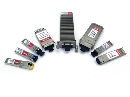
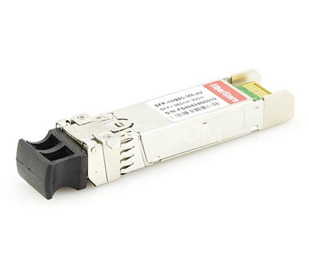
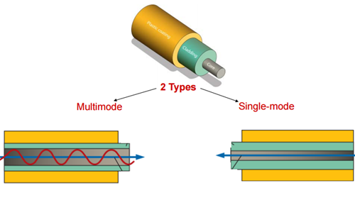
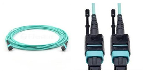
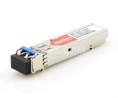
Cisco GLC-LH-SM is a 1000BASE-LX/LH SFP for both multimode and single-mode fibers. The 1000BASE-LX/LH SFP, compatible with the IEEE 802.3z 1000BASE-LX standard, operates on standard single-mode fiber-optic link spans of up to 10 km and up to 550 m on any multimode fibers. So now let’s move on the next part. Figure 1 shows a Cisco GLC-LH-SM transceiver module.
GLC-LH-SM
Every Network needs Cisco GLC-LH-SM
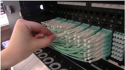
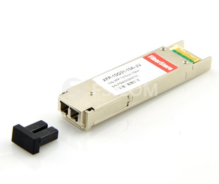
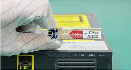
One thing that makes optical transceivers so special is that they are hot swappable—a huge development in fiber optic technology. In the past, if designers had to repair a transceiver failure, he would redesign the whole system, which meant a lengthy amount of network downtime. But with Cisco GLC-LH-SM, the whole process will be quite easy. You can leave the power on, remove the device, pop in the replacement, then you network is back off to races as shown in Figure 2.
Cisco GLC-LH-SM
It is necessary to make sure the configuration of an optical transceiver before operating. But this GLC-LH-SM transceiver is preferred by most designers because it doesn’t need to be configured to begin functioning. It is ideal for network designers as it reduces the number of steps required to achieve the desired goal. Sometimes, external calibration is required, but this is not always the case. The most stringent applications will require it, and most other applications will not. This significantly reduces the number of steps or requirements necessary for designing an optimal network.
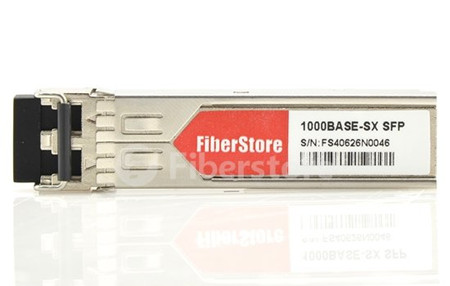
Cisco GLC-LH-SM is compatible with 1000BASE-LX/LH, which makes it possible for both single-mode and multimode fiber. When you need a network solution that covers a long distance, this transceiver operating over single-mode fiber is available for a link span of up to 10km. It is ideal to be deployed in Hospitals, university campuses, and large research facilities. And multimode opens the data floodgates, giving you maximum throughput upwards of 1.25 Gbps.
Conclusion
There lists three reasons why every network needs GLC-LH-SM transceiver. GLC-LH-SM fiber optic transceiver makes it so much easier to redesign fiber optic technology into your network. It does this, simply, by making it just as easy as to incorporate a traditional Ethernet router. And it doesn’t need to be configured. But besides those reasons, there are countless other reasons, which will help designers recognize why they should select the devices and design them into their networking solutions.
If you are in the market for GLC-LH-SM optics, ask an expert for help. He will help you select the proper technology and design what you need to achieve your goals. Every network needs GLC-LH-SM optics, you just have to find the best manufacturer and type to meet your needs. In fact, Cisco original fiber optics are too costly, the similar Cisco GLC-LX-SM-RGD are also very expensive. Thus find a reliable vendor will solve all your problems. As you know Fiberstore would love to answer any questions about GLC transceivers or any other networking questions you may have. Please contact us if you may have any questions.

Monday, April 25, 2016

Knowing the Features of Pluggable Optical Modules and Optical Patch Cables

Pluggable Optic modules are typically used in systems to leverage the rapid long data transmission distance of which fiber optic networks are capable. To realize the maximum distance, network designers must ensure that the integrating optical networks are robust and aware of the knowledge of the whole system—the types of optical modules and the electrical and optical standards for which the optical module is designed, and the host transceiver features that are required to transmit and receive data through an optical system. It seems to be troublesome process. So today’s article is intended to help designers overview the available options in the pluggable optical module market, along with the optical patch cables that must be considered when making design choices.
Pluggable Optical Modules Overview
When a designer looks at implementing an optical interface, several choices need to be made based on the protocol and application. Take optical transceiver module as an example, to select a suitable transceiver module, you need to take the following factors into consideration—types of optical modules, different form factors, features, electrical and optical specifications, and lane width, etc. Figure 1 shows several pluggable optic transceivers. Can you recognize them?
pluggable optic tranceivers
Optics have a long history of use in the telecommunications sector. As a result, there is a wide variety of form factors that are available for optical modules. To simplify the discussion, this article focuses on the current set of optical modules utilized for 10G, 40G, and 100G Ethernet, though many of the topics translate directly to OTN or other standards. These Ethernet rates can be supported by a variety of electrical lane widths (usually one, four, or ten lanes), which in turn determine the electrical line rates. For example, either four lanes of 3.125 Gb/s or a single lane of 10.3125 Gb/s can support 10G Ethernet; similarly, either ten lanes of 10.3125 Gb/s or four lanes 25.78125 Gb/s can support 100G Ethernet. The current crop of high-end optical modules leverages a base rate of 10.3125 Gb/s, for 10G, 40G, and 100G Ethernet in one, four, or ten lanes. Popular optical modules are available that support each of these widths at this rate: SFP+ or XFP for a single lane, QSFP+ for four lanes, and CFP for ten lanes. Take XFP-10GLR-OC192SR as an example, it is XFP compatible 10GBASE-LR/LW transceiver with a maximum data rate of 10.3125Gbps over single lane. Module type is constrained only by its form factor and pinout, supporting a variety of electrical and optical standards. This large field of choice adds to the complexity of selecting the correct parts for design into a system.
Impact of Optical Fiber on a System
One common difference between modules is the length and type of fiber a module can drive. SFP+ makes itself a good example for examining the options. 10G Ethernet defines a number of optical interfaces (SR, LR, LRM, and ER) along with other industry adopted standards (ZR and DWM) that specify the optical wavelength and the length and type of optical fiber that can be supported. Each element of this selection has a different impact on the link performance. For example, 10GBASE-SR (e.g. SFP-10GB-SR) uses an 850nm wavelength and can support up to 300m of 50µm multimode fiber while 10GBASE-LR uses a 1300nm wavelength and can support 10 km of single mode fiber.
Fiber Optic Patch Cable Overview
Choose a fiber optical cable is largely on the selection of multimode and single-mode fiber. The differences between multimode fiber and single-mode fiber are important. Single-mode fiber consists of a single strand of fiber that the data is transmitted across. Multimode fiber is composed of multiple strands of fiber bundled together, where light can pass across each strand. In either case, an effect known as dispersion can impact the fidelity of the transmit signal. As the signal passes through the fiber, the distribution of wavelengths of light that contain signal content are interacted with in slightly different ways, some wavelengths experiencing more delay or varying degrees of attenuation. The impact of this optical dispersion to the waveform is distinctly different from how copper impacts electrical signals. As a result, high levels of optical dispersion require special circuitry to compensate for, typically in the form of a feed-forward equalizer (FFE) in conjunction with the standard DFE and CTLE structures used for electrical channels. Figure 2 shows LC multimode fiber optic patch cable plugging in adapter panel.
lc multimode-fiber-patch-cable
While both single-mode and multimode fiber introduce some dispersion, the single-mode has the advantage that very little dispersion occurs per unit length compared to multimode fiber, leaving loss as the primary contributor to signal degradation at the far end of the link. The amount of dispersion introduced in multimode fiber varies depending on the laser wavelength. At 850 nm (used for 10GBASE-SR), very little optical dispersion is introduced over the maximum 300m of fiber. Comparatively, at 1300 nm (used for 10GBASE-LRM), far more dispersion is introduced—enough that it needs to be compensated for after the signal is translated into the electrical domain.
Conclusion
Fiber optics is becoming a standard part of today's high-bandwidth landscape. Designers using optics are faced with a wide variety of choices of implementation rates, form factors, optical standards, electrical standards and the trade-offs between them. Knowing how the features of a given optical module impact the rest of the system is an advantage that cannot be ignored. Fiberstore is dedicated to supporting a wide variety of optical interfaces at today's 10Gb/s standards and beyond. We provide pluggable optical modules from 1G SFP modules to 100G CFP2 modules, as well as offering a full range of optical cables. For more information on how to implement optical interfaces, you are welcome to contact us.

Wednesday, April 20, 2016

How Much Do You Know About Push-Pull Patch Cable?

It is known that fiber optic patch cables are normally named after optical connector or the fiber type, thus people can differentiate optical patch cables according to their names. Today a new fiber optic patch cable—push-pull patch cable is developed to provide high-density performance. Can you tell what this type of cable is used for? Why use push and pull to describe this patch cable? And what is the unique advantage over traditional patch cables? The following articles will provide a satisfying solution to you.
Push-Pull Patch Cable Overview
The world is marching towards big data age, and data centers are upgrading to 40/100G Ethernet and beyond, which is a goods news for users, but a real problem for network designers. In order to keep the path with customers’ requirement, network designers are supposed to put forward a cost-effective solution. Other than adding more floor space, they prefer to increase the power density of the data center. Therefore, push-pull tab patch cables are created.
push-pull-tab-patch-cords
Push-pull patch cable (or push-pull tab patch cable) is a new patch cord with a unique connector design that can help to solve the problems of finger access in high-density cabling as shown in Figure 1. Push-pull tab patch cable has the same components and internal-structure as the traditional patch cords, except a tab attached to the connector used for pushing or pulling the whole connector. With this connector design, technicians can finish the installing and removing procedures with only one hand and no additional tools are needed.
Nowadays, this high-density push-pull patch cable, with either MPO or LC connector, is widely used in 40G and 100G network cabling. LC-HD TAB fiber patch cables and MPO-HD TAB fiber patch cables are the two common types of push-pull tab patch cable available on the market. Though traditional patch cables are also popular in the data center, the push-pull tab patch cables are superior in the following aspects.
Easy Installation
It is usually difficult to disengage the traditional patch cords because its duplex latch of the patch cord often sits underneath the base of the connector above. But push-pull patch cable with this new ‘Pull’ tab design, the latch is extended out to the space in front of the connector, making it easy to pull and disengage the patch cord.
push-pull patch cable
Higher Flexibility and Adjustability
Push-pull patch cords are utilized in various specifications which can connect different generation of devices from 10Gb/s to 120Gbp/s or more. It provides safe and easy push and pull of the specific connector without affecting the other connectors around it. Additionally, the initial investment cost may be reduced for the high-density and easy-installation feature.
Space-saving
The traditional connectors often require a small vertical space above and below the adapters. While the low profile push-pull TAB patch cable, together with its pull tab, allow adapters to be stacked with absolutely no vertical space.
Conclusion
Push-pull tab patch cables with its unique connector design, provides improved accessibility, reduced installation costs and outstanding performance to meet the never-ending requirement for high-density data center applications. Fiberstore provides a full range of push-pull patch cables that will help free up space. We have simplex&duplex LC-HD patch cords, 12&24 fibers MPO-HD patch cords, MPO-LC harness cables, Push-Pull LC patch cable, providing low-loss performance for multi-mode and single mode high speed networks and improving network performance. If you have any inquiry of our products, please contact us directly.

Thursday, April 14, 2016

Juniper 10-Gigabit Ethernet Optical Transceivers – EX-SFP-10GE-SR and XFP-10G-L-OC192-SR1

From the emergence of 10G Ethernet, 10G optical transceivers have been developed along the way to meet the increasing requirement for high performance. From the old XENPAK to X2, XFP, SFP+, optical transceiver becomes smaller, more affordable and less power hungry, which might be a good news for 10G deployment. But with so many options available on the market, it is difficult for users to select a matching transceiver for their given application and hardware.
In fact, as the first 10G optical transceiver, XENPAK gradually exits the stage. Few people today would choose to use XENPAK and X2 for 10G connectivity. At the same time, XFP and SFP+ are offered by many vendors with different specifications. Of which Juniper XFP and SFP+ win a large market share. Today’s post will go on to talk about Juniper XFP and SFP+ transceiver module.
SFP+ Transceiver
The enhanced small form-factor pluggable (SFP+) is an upgraded version of the former SFP. SFP+, compared with the XENPAK and X2, possesses more compact size with data rates up to 10 Gbit/s. And it can also support 8Gbps/10Gbps/16Gbps Fibre Channel, 10 Gigabit Ethernet and Optical Transport Network standard OTU2. The SFP+ product family includes cages, connectors, and copper cable assemblies. In addition, they have the ability to connect to a variety of different types of optical fiber and are highly flexible. That’s why they are so desirable to designers.
Juniper EX-SFP-10GE-SR
Take Juniper EX-SFP-10GE-SR as an example, this SFP+ transceiver module is designed for use with Juniper network equipment and is fully compatible with Juniper switch and routers. This Juniper EX-SFP-10GE-SR is 10GBASE-SR SFP+ that operates over a wavelength of 850nm. It combines quality with low cost and gives you an ideal alternative except for the high price transceivers. Here are some key features of the optical transceiver.
EX-SFP-10GE-SR
Feature
  • Functionally identical to Juniper Networks EX-SFP-10GE-SR
  • LC ports designed for use with multimode fiber
  • Includes Digital Optical Monitoring (DOM)
  • 850nm wavelength signaling
  • Supports up to 300 meters of cabling
XFP Transceiver
XFP transceiver is a hot-pluggable and protocol-independent 10 Gbit/s optical transceiver designed to help drive cost and power consumption out of 10 Gbit/s optical networking applications. This particular XFP specification was developed by the XFP Multi-Source Agreement Group. XFP transceivers are capable of operating at wavelengths of 850 nm, 1310 nm, and 1550 nm at a single wavelength or through the use of dense wavelength-division multiplexing techniques. There are a variety of transceiver types available, but the most popular ones include: SR (850 nm and can transmit up to 300 m), LR, ER, and ZR. LR is 1310 nm and can transmit distances up to 10 km.
Juniper XFP-10G-L-OC192-SR1
XFP-10G-L-OC192-SR1 is Juniper 10GBASE-LR XFP transceiver. It operates at a wavelength of 1310nm with a link length of up to 10km links. ER is characterized by 1550 nm and can transmit distances of 40 km. ZR can transmit distances up to 80 km. Designers prefer to use XFP packaging because it has a smaller footprint than other devices. And this XFP-10G-L-OC192-SR1 is fully compatible with all Juniper series switches and modules which support XFP transceivers. The following are some detailed information about this product.
XFP-10G-L-OC192-SR1
Technical Performance
Module model: XFP
Device Type: Transceiver module
Interface (Bus) Type: Plug in module
Connectivity Technology: Wired
Application: 10GBASE SR1
Product working data rate: 10Gbps
Wavelength: 1310nm
Max Distance: 10km
Fiber Type: SMF
Connector: Duplex LC
DDM: With DDM
Operating Temperature: 0~70 °C
Compliant with MSA XFP Specification
3rd-party Optical Transceiver Recommendation
For your limited budget, 3rd-party optical modules may be good choice. Just remember to find a reliable vendor. Fiberstore has a large quantity in stock transceivers and can ship in very short time. You will find the cost-effective and high-quality Juniper XFP-10G-L-OC192-SR1 and EX-SFP-10GE-SR beyond your expectation. Additionally, customize optical transceivers to fit your specific requirements are available. Contact us today to save the time and cost by buying from us directly.

Tuesday, April 12, 2016

1000BASE-SX SFP Transceivers for Gigabit Ethernet

Standardized by the IEEE, Gigabit Ethernet is a term describing various technologies for transmitting Ethernet frames at a rate of a Gigabit per second, which has been considered to be a viable solution for increased bandwidth requirements for growing networks. 1000BASE SFP transceiver is a hot-pluggable input/output device that plugs into a Gigabit Ethernet port/slot, linking the port with the network. Recently the market is flooded with various 1000BASE SFP transceivers available for Gigabit Ethernet. With so many options out there in the market, people may feel puzzled about how to select the one that is in in accordance with their application. Therefore the following article will make a brief introduction to the 1000BASE SFP to help you choose the most suitable one.
Fiber-based or Copper-based Gigabit Ethernet
According to cable material, Gigabit Ethernet can be classified into fiber-based Gigabit Ethernet and copper-based Gigabit Ethernet. In fiber-based Gigabit Ethernet, 1000BASE-X is used to refer to Gigabit Ethernet transmission over fiber. 1000BASE-X is a group of standards for Ethernet physical layer standards. These standards include: 1000BASE-SX (A fiber optic Gigabit Ethernet standard for operation over multi-mode fiber), 1000BASE-LX (a fiber optic Gigabit Ethernet standard using a long wavelength laser and a maximum RMS spectral width of 4 nm), 1000BASE-LX10 (which is very similar to 1000BASE-LX, but achieves longer distances over a pair of single-mode fiber), 1000BASE-BX10 (which is capable of up to 10 km over a single strand of single-mode fiber) or the non-standard 1000BASE-EX ( a industry accepted term to refer to Gigabit Ethernet transmission) and 1000BASE-ZX (a multi-vendor term to refer to Gigabit Ethernet transmission) implementations.
While for copper-based Gigabit Ethernet, 1000BASE-CX, 1000BASE-KX, 1000BASE-T and 1000BASE-TX are four standards for Gigabit Ethernet over copper wiring. 1000BASE-CX uses copper cables as a medium. 1000BASE-KX is part of the IEEE 802.3ap standard for Ethernet Operation over Electrical Backplanes. 1000Base-T uses four pairs of Category 5 unshielded twisted pair cables to achieve Gigabit data rates. 1000BASE-TX is similar to 1000BASE-T but uses two pairs of wires rather than four for data transmission.
1000BASE SFP Transceivers for Gigabit Ethernet
1000BASE SFP transceiver is a device that interfaces a network device motherboard to a fiber optic or copper networking cable. It is designed to support Gigabit Ethernet, Fibre Channel and other communications standards. As noted before, there are 1000BASE optical SFP transceivers and 1000BASE copper SFP transceivers used in Gigabit Ethernet. The following part will go on to talk about one of the 1000BASE optical SFP transceivers—1000BASE-SX SFP.
The 1000BASE-SX is one of the physical layer standards for Gigabit Ethernet, meaning the single optic fiber 1000Mbps baseband transmission standard. “S” refers to short-range multimode optical cable, while “X” means 4B/5B block coding for Fast Ethernet or 8B/10B block coding for Gigabit Ethernet. The standard specifies a transmission distance between 220 m and 550 m. It is highly popular for intra-building links in large office buildings, co-location facilities and carrier neutral internet exchanges. Therefore, 1000BASE-SX SFP transceiver module is the best seller in those fields.
Two 1000BASE-SX SFP Transceivers
The 1000BASE-SX SFP transceiver module is compatible with the 1000BASE-SX standard. It can support up to 1km over laser-optimized 50μm multimode fiber cable. The wavelength range that 1000BASE-SX SFP transceiver module transmits and receives is from 770nm to 860nm. Fiberstore provides a variety of 1000BASE-SX SFP transceivers that are fully compatible with other brands. Take AA1419048-E6 and TL-SM311LM as an example.
AA1419048-E6AA1419048-E6 is Avaya Nortel 1000BASE-SX SFP transceiver module for multimode fiber. It is the multimode module with a wavelength of 850nm. Avaya Nortel 1000BASE-SX SFP transceiver module supports hot-pluggable SFP footprint duplex LC connector Interface. This transceiver is built to comply with Multi-Source Agreement (MSA) standards. AA1419048-E6 supports dual data-rate of 1.25Gbps/1.0625Gbps, which is widely used in fiber channel links, Gigabit Ethernet links, Fast Ethernet links, other optical links.
AA1419048-E6
TL-SM311LMBesides AA1419048-E6, TL-SM311LM from TP-LINK is also available in the market for supporting Gigabit Ethernet Application. TL-SM311LM has the same specification with other 1000BASE-SX SFPs, which supports a link length of up to 550m on multimode fiber.
As there are different physical layer standards for Gigabit Ethernet, different 1000BASE SFP transceivers may be used for different application. These 1000BASE SFP transceivers can be used for single-mode and multimode fibers of different reaches. 1000BASE-SX SFP transceiver can operate link spans of up to 550m on any multimode fibers. Fiberstore produces a variety of compatible 1000BASE SFP with high quality and low prize including the above two SFP transceivers. We can also customize optic transceiver to meet your specific requirements. If you have any interest, please send your request to us.

Thursday, April 7, 2016

How to Ensure Good Performance of Fiber Optic System?

We all know that transmission system is the key part of a fiber optic system. The performance of transmission system can directly affect the performance of fiber optic system. So what is the transmission system? The transmission system is a system that transmits a signal from one place to another. If you want to make sure the good performance of a fiber optic system, you should first ensure the transmission system in a good state. Next, today’s article will give you a list of basic items that may affect general transmission system performance. Only understand the following aspects can you know how to ensure the good performance of fiber optic system.
Fiber Loss Factor
Fiber loss generally has the greatest impact on overall system performance. The fiber strand manufacturer provides a loss factor in terms of dB per kilometer. A total fiber loss calculation is made based on the distance x the loss factor. Distance in this case the total length of the fiber cable, not just the map distance.
Type of Fiber
Most single-mode fibers have a loss factor of between 0.25 (1550nm) and 0.35 (1310nm) dB/km. Multimode fibers have a loss factor of about 2.5 (850nm) and 0.8 (1300nm) dB/km. The type of fiber used is very important. Multimode fibers are used with L.E.D. transmitters which generally don't have enough power to travel more than 1km. Single mode fibers are used with LASER transmitters that come in various power outputs for "long reach" or "short reach" criteria.
single-mode-vs-multimode
Transmitter
There are two basic type of transmitters used in a fiber optic systems. LASER which come in three varieties: high, medium, and low (long reach, medium reach and short reach). Overall system design will determine which type is used. L.E.D. transmitters are used with multimode fibers, however, there is a "high power" L.E.D. which can be used with Single mode fiber. Transmitters are rated in terms of light output at the connector, such as -5dB. A transmitter is typically referred to as an "emitter".
Receiver Sensitivity
The ability of a fiber optic receiver to see a light source. A receiving device needs a certain minimum amount of received light to function within specification. Receivers are rated in terms of required minimum level of received light such as -28dB. A receiver is also referred to as a "detector".
Number and Type of Splices
There are two types of splices. Mechanical, which use a set of connectors on the ends of the fibers, and fusion, which is a physical direct mating of the fiber ends. Mechanical splice loss is generally calculated in a range of 0.7 to 1.5 dB per connector. Fusion splices are calculated at between 0.1 and 0.5 dB per splice. Because of their limited loss factor, fusion splices are preferred. The following image vividly shows a good fiber connectivity and bad fiber connectivity, which may make a big difference in the insertion loss.
clean
dirt
Margin
This is an important factor. A system can't be designed based on simply reaching a receiver with the minimum amount of required light. The light power budget margin accounts for aging of the fiber, aging of the transmitter and receiver components, addition of devices along the cable path, incidental twisting and bending of the fiber cable, additional splices to repair cable breaks, etc. Most system designers will add a loss budget margin of 3 to 10 dB.
Selecting the Right Fiber Optic Cable
Of course, only knowing this is not enough. Fiber optic cable always plays an important part in the transmitting system. As a result, the quality of the fiber optic cable is of vital value to the whole fiber link. To choose a fiber optic cable, you need to know the following:
First: what type and grade of fiber is required? The system designer will have identified the fiber that is required for the network. Find the fiber type that is needed from the Fiber Specification and Selection Guide. Use the Fiber Type code to identify the fiber. This code becomes the first two digits of the catalog part number, replacing the XX notation. There are two common types of fiber optic cables—singlemode and multimode fiber optic cables.
fiber type
Then, how many fibers are required? The system designer will also have identified the number of fibers that will be in each cable. Fibers are usually cabled in groups of 6, 12, 24, 48, or 72.
Last but not least: what cable construction is needed? The cable construction that is needed is based on a variety of factors. We have a full range of products for premises, outside plant and indoor/outdoor to solve nearly every application need. Using the catalog as a guide, identify the cable type and construction that is needed. For example, Pull tab LC cable is a type of cable that uses MPO-HD to LC-HD Push Pull TAB connector.
Summary
To ensure the better performance of your fiber optic system, you are supposed to keep the above recommendations in your mind firmly. If you feel puzzled about how to ensure the better performance of your fiber optic system, you can also turn to a reliable vendor to help you out. Fiberstore as a rising telecom manufacturer, is committed to provide first-class services and high-quality products to our customers. For fiber optic cables, you can find many kinds with good quality and reasonable prices in FS.COM. A new type of fiber optic cable (Push-Pull patch cable) is also provided. Any questions, please feel free to contact us.

Tuesday, April 5, 2016

MPO Cable Testing Overview

Nowadays, the existing bandwidth is not adequate to meet enterprises’ increasing appetite. In the meanwhile, optical technologies like cloud computing, virtualization and storage area networks are all in the fast development, which pushes the further development of higher-bandwidth tech like 40/100G Ethernet. Thus under this circumstance, new devices are greatly required. Besides the new optical transceivers and fiber optic cables, a steady proliferation of fiber connections—MPO (Multifiber Push-On) came into being.

MPO cables, featured by its compact, pre-terminated advantages, has become the default cabling solution for the increasing bandwidth requirements. However, a flaw of the MPO cable may hinder its development. The testing process of the MPO cable can be complex and error-prone. Have you been through the scene? When you prepare to test a MPO cable, you have to throw polarity of all 12 fiber connections into the mix. And if it comes to migrating 10 Gbps to 40/100 Gbps on the same cable, all the testing job you have done is in vain. Since the testing process is pretty uneasy, The following text will provide some detailed information about it to help you do the right MPO cable testing.

MPO cable 

Problems You Should Know About MPO Cable Testing
Typically, a MPO cable contains 12 optical fibers, and each fiber is thinner than human’s hair. So if you want to test the cable, you must test every fiber of it, which is quite difficult for inexperienced engineers. The common way to do this is to use a fan-out cord to make the 12 fibers separate, then testing. One fiber testing would take you 10 seconds. So if your customer ask you to test 48 MPO trunks cable in data center which has a 30,000-MPO data center installation, that means you need to spend 3,120 hours. Such a huge project! To avoid this expensive and time-consuming process, modular factory-terminated MPO cables promise simplicity, lower cost, and true plug-and-play fiber connectivity.

Additional, when you are about to test a MPO cable, you should check whether the MPO cable is in the good state. Because cables must be transported, stored, and later bent and pulled during installation in the data center, which may lead to the performance uncertainties before fiber cables are deployed. Proper testing of pre-terminated cables after installation is the only way to guarantee performance in a live application.

What’s more, fiber polarity is also an important factor you should take into account. The simple purpose of any polarity scheme is to provide a continuous connection from the link’s transmitter to the link’s receiver. For array connectors, TIA-568-C.0 defines three methods to accomplish this: Methods A, B and C. Deployment mistakes are common because these methods require a combination of patch cords with different polarity types.

The Relationship Between Bandwidth and Testing
The market trend of telecom industry implies that 10G network has already been deployed in a large scale. And now 40G is main stream. As for 100G, people also already prepare for it. So bandwidth would always be a hot topic.

We have said before that MPO cable can solve the problem of bandwidth. As data center bandwidth steadily climbs to 10, 40, and 100Gbps, a dense multi-fiber cable becomes the only option. That’s why the use of MPO cables has steadily risen over the past 10 years. With the MPO cabling system, 40/100G migration path seems to be a simple and easy solution. Just remove the 10Gbps cassette from the MPO cable and replace it with a bulkhead accommodating a 40Gbps connection. Later it might be possible to remove that bulkhead and do a direct MPO connection for 100 Gbps at a later date. Figure 2 shows a 40G connectivity with the use of the 12-fiber MPO cable. A 40G QSFP like QSFP-40G-SR4 connects to a 12-fiber MPO cable. A 12-fiber MPO fanout cable is also used to connect four 10G SFP+ transceivers like 46C3447 with a MPO FAP.

40G connectivity
The problem is that while this migration strategy is an efficient way to leverage the existing cabling, in comparison to 10Gbps connections, the 40Gbps and 100Gbps standards call for different optical technology (parallel optics) and tighter loss parameters. In short, each time you migrate you need to verify the links to ensure the performance delivery the organization requires.

How to Do the Proper MPO Cable Testing
When you move to this part, you may think that MPO testing may be a tough obstacle for us to conquer. So is there a simple way to do the testing? The answer is yes. You can just test all 12 fibers—the whole cable—simultaneously and comprehensively (including loss and polarity). That sort of test capability changes the fiber landscape, enabling installers and technicians to efficiently validate and troubleshoot fiber—flying through the process by tackling an entire 12-fiber cable trunk with the push of a button.

MPO cable testing tool
To do a proper MPO cable testing, you must need some proper testing tools as shown in Figure 3. The tools to perform this type of test are emerging on the market, and promise to reduce the time and labor costs up to 95% over individual fiber tests. Characteristics to look for in such a tool include the following parts.
  • An onboard MPO connector to eliminate the complexity and manual calculations associated with a fan-out cord.
  • A single “Scan All” test function that delivers visual verification via an intuitive interface for all 12 MPO fibers in a connector.
  • Built-in polarity verification for end-to-end connectivity of MPO trunk cables.
  • “Select Individual Fiber” function that enables the user to troubleshoot a single fiber with more precision.
Summary
The insatiable need for bandwidth ensures that the integrity of the data center, which has also become inextricably linked to the strength of the fiber cabling infrastructure. Now more and more MPO trunk cables are put into use, to make sure the better performance, you should be able to test the MPO connection. Fiberstore offers a variety of MPO products including MPO trunk cables, MPO harness cable, 12-fiber or 24-fiber MPO cable and so on. All of our products can also be customized. Please feel free to contact us.